IEC 60870 Server
Overview
This feature is available starting with PROCON-Connect v1.4.0.
The IEC 60870 server in PROCON-Connect provides process data and status information for higher-level control systems. It enables plant components to be reliably integrated into energy distribution and automation structures. The server receives and processes IEC 60870 telegrams and makes the information they contain available in the form of tags within PROCON-Connect.
This tag mapping seamlessly integrates measured values, switching commands, events, and status information from IEC 60870 telegrams into the software. The data can then be used for process connections, logic and function modules, visualizations, and for forwarding to other protocols. The IEC 60870 server thus serves as a central interface for securely and flexibly integrating IEC-compliant field devices into the overall architecture of PROCON-Connect.
Server overview
An overview of how to manage existing servers and a starting point for adding new servers.
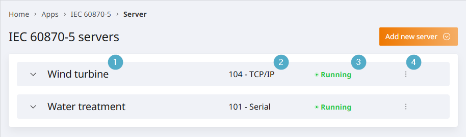
Name: The unique name of the server. This can be chosen freely when adding the server and is used solely for identification purposes in the overview.
Server type: The server can be type 104 (TCP) or 101 (serial). The server type affects the configuration options when adding a server, as well as its communication protocol.
Client connections: Number of client connections. Clicking this opens the connection overview. The connection overview displays the address and Status for each client.
Status: Possible statuses are
Running,Stopped,ErrororUnlicensed. Only an active server can send and receive messages.Options menu: The starting point for manually adding information objects, importing information objects, or editing and deleting the server.
Connection status of clients
Possible statuses are ‘Connected, inactive’ and ‘Connected, active’.
The server only sends values to active connections. Activation is initiated by the client. The behaviour in the event of multiple activations can be configured on the server side; see Redundancy.
Configure the server
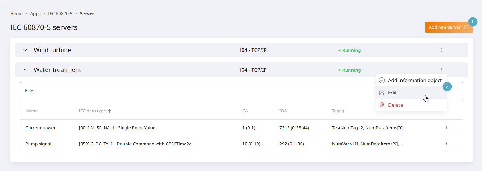
The following parameters can be configured on a server:
Name: The server’s name is displayed on the overview page and is intended to make it easier to identify the server.
Enabled: This setting can be used to enable or disable the server. Only an active server can send and receive messages.
Allow time synchronisation: Allows clients to set the server’s system time (IEC Type 103 time synchronisation). May require advanced system privileges, particularly on Windows. May disable automatic time synchronisation (NTP) on the system. It is recommended that you disable this setting and use the operating system’s NTP mechanism instead.
Use UTC time: By default, the local time of the operating system (u-OS, Linux, Windows) is used. UTC time can be used by enabling this option. All clients and servers must be configured in the same way. This affects the interpretation of received timestamps and the timestamps on outgoing messages.
Pulse Configuration: The parameters defined here determine how long the outputs are set when a pulse command is executed. Pulse handling is handled by the 60870 server.
Default duration (ms): Specifies the default pulse duration used for control commands when no alternative pulse duration is specified. Typically in the range 50–500 ms.
Short duration (ms): Defines a shortened pulse duration for specific control commands that require minimal time.
Duration (ms): Sets the extended pulse duration.
Connection status tag mapping: Mapping of the connection status to a logical or numeric tag.
Logical tag: 0 = No clients connected. 1 = At least one client connected.
Numeric tag: 0 = no clients connected. n = n clients connected. Example: 2 = 2 clients connected at the same time.
Configuring the 104 server
These parameters are specific to 104:
Server address: The binding address and port through which the server should be accessible. The default port is 2404. In u-OS, the binding address and port cannot be configured; the address 0.0.0.0 and port 2404 are always used.
T1: Timeout for transmitted APDUs in I/U format (in seconds). If the timeout expires without an acknowledgement, the connection is closed. This is used by the sender to determine whether the receiver has failed to acknowledge a message.
T2: Time limit for message acknowledgement (in seconds). This time limit is used by the recipient to determine the point in time by which the message acknowledgement must be sent.
T3: Time limit for sending test telegrams when the connection is inactive.
K: Number of unacknowledged APDUs in I-format. The sender terminates the transmission after
Kunacknowledged I-messages.W: Number of unacknowledged APDUs in I-format. The recipient will acknowledge them after no more than
Wmessages.Low-priority queue size: Used for cyclic and event/spontaneous data transmissions. The queue operates on a FIFO basis. If the queue is full when a new telegram is added, the oldest telegram is removed.
High-priority queue size: Used for responses to commands. The queue operates on a FIFO basis. If the queue is full when a new telegram is added, the oldest telegram is removed.
Client Whitelist
Whitelisting allows you to specify as many IP addresses as you like. By default, the list is empty and any client can connect to the server.
The following mechanics apply:
If no client has been created, connections from all clients are allowed; no IP-based verification takes place.
If at least one client has been created, only connections from listed clients whose ‘Enabled’ parameter is active will be permitted.
If only clients are listed and they are all disabled, clients will not be able to establish a connection at all.
Redundancy
The redundancy configuration controls the server’s behaviour in response to activation requests from clients. This behaviour is controlled via redundancy groups. A client is always in exactly one redundancy group. Redundancy groups can contain between 1 and n clients.
Within a redundancy group, only one client can have an active connection. If a connection to a client within the redundancy group already exists at the time of activation, that connection is deactivated. Active connections in other redundancy groups remain unaffected.
Only one active connection: All clients are in a single redundancy group. Only one connection is active; all other connections are on standby. When a client becomes active, it deactivates any client that may have been active previously. This is the default setting.
All connections active: Each client has its own redundancy group. When a client establishes a connection, this takes place in parallel with any other clients that may already be active. There is no limit on the number of parallel connections.
Manual redundancy group assignment: Redundancy groups and their associated clients can be created in two stages. A group name can be assigned to redundancy groups to facilitate identification. Individual redundancy groups can be enabled or disabled via the UI. Using the
+button, any number of client addresses (IP addresses) can be assigned to a redundancy group.
Configuring the 101 server
These parameters are specific to 101:
Serial port: The name of the serial port to be used for communication, e.g. COM1.
Baud rate: The speed of physical data transmission in bauds. The default is 9600.
Data bits: Number of data bits. The default is 8.
Stop bits: Number of stop bits. The default is 1.
Parity: None, even or odd parity can be set. The default is None.
Mode: Connection mode. Possible options are unbalanced and balanced. The default is unbalanced.
Address length (bytes): Address length in bytes. The default is 1 byte.
Confirmation timeout (ms): Timeout for confirmation. The default is 500 ms.
Local link-layer address: The default is 1.
Remote link-layer address: The default is 1.
Common Address (CA) – Bytes: Length of the CA in bytes. Can be 1 or 2 bytes. The default is 2.
Information Object Address (IOA) – Bytes: Length of the IOA in bytes. Can be 1 to 3 bytes. The default is 3.
Transmission cause (COT) – Bytes: Length of the CA in bytes. Can be 1 or 2 bytes. The default is 2.
Overview of information objects
To access the information object overview, first navigate to the IEC 60870-5 server overview page. Clicking on a server entry opens its information object overview.
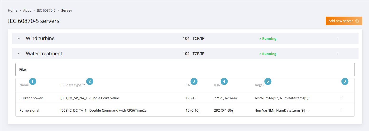
Name: Name of the information object. Displayed in the information object overview. Optional.
IEC data type: The data type of the information object.
CA: The information object’s shared address in dual notation: integer and byte-by-byte.
IOA: Information object address in dual notation: integer and byte-by-byte.
Tags: A list of all tags assigned to the information object.
Options menu: The starting point for editing or deleting an existing information object.
When configuring information objects, multiple tags are assigned. The link between an information object and tags is established via dependencies. The configuration is automatically checked for consistency when the overview is opened. Any inconsistencies are indicated by a warning triangle in the first column of the information object overview. Further information is displayed in a tooltip when the mouse pointer is positioned over the warning triangle. During the check, the value ranges of the assigned tags are examined in conjunction with the IEC data type.
Configure information objects
Add information object (1).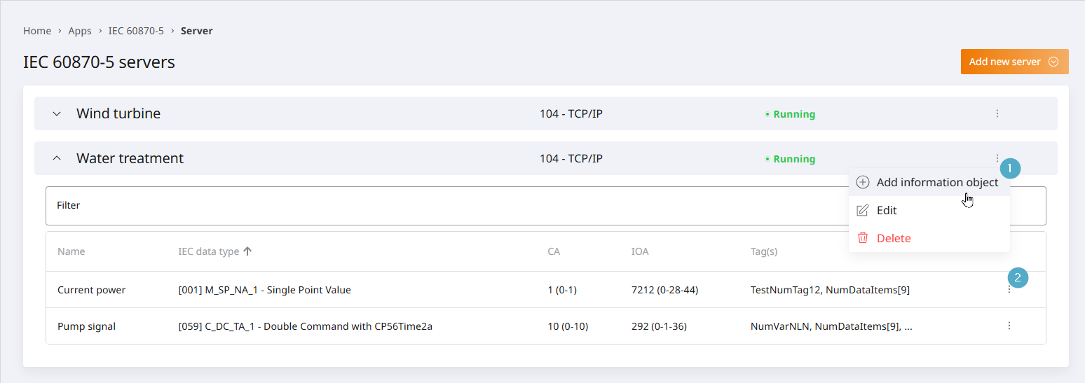
General parameters
The following parameters can always be configured in an information object. These parameters are not dependent on the IEC data type.
Name: Name of the information object. Displayed in the information object overview. Optional.
Common Address (CA): The CA can be entered in the left-hand field as a single number or in the right-hand field byte by byte. [1; 65534] are station addresses; 65535 is the global address.
Information Object Address (IOA): The IOA can be entered as a single number in the left-hand field or byte by byte in the right-hand field.
IEC data type: The IEC data type can be selected from a drop-down menu. The selection affects the configuration options below, such as the available tag mappings.
Parameters in the monitoring direction
The following parameters are available on the server for all IEC data types in the monitoring direction:
General query: The information object is included in the response to the general query.
Group interrogation: Information objects in the monitoring direction can be assigned to groups. Any number of groups can be assigned in parallel. It is also possible to combine this with the general query.
Cyclic transmission (COT1): Information objects in the monitoring direction can be transmitted cyclically.
Event/Spontaneous Transmission (COT3): Information objects in the monitoring direction can be transmitted when their values change. Absolute and percentage thresholds can be defined, by which the value must have changed compared to the last transmission.
Depending on the IEC data type, the following tag mappings in the monitoring direction are possible:
Value: The tag whose value is to be transferred.
Invalid (IV): Numeric or Boolean tag that represents the
Invalidquality bit. This bit is automatically set if the tag’s quality contains an error code (not OK, LOW_OUT, or HIGH_OUT).Not topical (NT): A numeric or Boolean tag representing the
Not Topicalquality bit.Substitute value (SB): A numeric or Boolean tag that represents the
Substitutedquality bit.Blocked (BL): Numeric or Boolean tag representing the
Blockedquality bit.Overflow (OV): Numeric or Boolean tag that represents the
Overflowquality bit. This bit is automatically set if the tag’s quality contains the code LOW_OUT or HIGH_OUT. The value is set to the allowed minimum/maximum.Transient: A Boolean tag that indicates whether the information object is currently in a transient state. “true = transient state”, “false = steady state”.
Timestamp: The tag containing the timestamp. If no tag is selected, the most recent timestamp from the other tag assignments (Value, Quality, Transient) is used. The source of the timestamp depends on the driver. For driver-specific details, see Driver settings.
IEC data type |
Value |
Quality |
Transient |
Timestamp |
|---|---|---|---|---|
[001] M_SP_NA_1 - Single Point Value |
x |
x |
||
[003] M_DP_NA_1 - Double Point Value |
x |
x |
||
[005] M_ST_NA_1 - Step Position Information |
x |
x |
x |
|
[009] M_ME_NA_1 - Measured Value, Normalized |
x |
x |
||
[011] M_ME_NB_1 - Measured Value, Scaled |
x |
x |
||
[013] M_ME_NC_1 - Measured Value, Short |
x |
x |
||
[015] M_IT_NA_1 - Integrated Totals |
x |
x |
||
[021] M_ME_ND_1 - Measured Value Without Quality |
x |
|||
[030] M_SP_TB_1 - Single Point Value with CP56Time2a |
x |
x |
x |
|
[031] M_DP_TB_1 - Double Point Value with CP56Time2a |
x |
x |
x |
|
[032] M_ST_TB_1 - Step Position Information with CP56Time2a |
x |
x |
x |
x |
[034] M_ME_TD_1 - Measured Value, Normalized with CP56Time2a |
x |
x |
x |
|
[035] M_ME_TE_1 - Measured Value, Scaled with CP56Time2a |
x |
x |
x |
|
[036] M_ME_TF_1 - Measured Value, Short with CP56Time2a |
x |
x |
x |
|
[037] M_IT_TB_1 - Integrated Totals with CP56Time2a |
x |
x |
x |
Parameters in the command direction
Depending on the IEC data type, the following tag mappings in the command direction are possible:
Value: The tag whose value is to be transferred.
Qualifier: A tag containing quality information. The quality information is represented by an integer.
Select/Execute: A Boolean tag that can be used to prepare messages.
true = Execute,false = Select.Transmission cause: A tag containing information on whether the command is an ACTIVATION or a DEACTIVATION. This can be evaluated in the PLC to cancel the execution of a command currently in progress.
Timestamp: The tag containing the timestamp. If no tag is selected, the most recent timestamp from the other tag assignments (Value, Quality, Transient) is used. The source of the timestamp depends on the driver. For driver-specific details, see Driver settings.
IEC data type |
Value |
Qualifier |
Select/Execute |
Cause of transmission |
Timestamp |
|---|---|---|---|---|---|
[045] C_SC_NA_1 - Single Command |
x |
x |
x |
x |
|
[046] C_DC_NA_1 - Double Command |
x |
x |
x |
x |
|
[047] C_RC_NA_1 - Step Command |
x |
x |
x |
x |
|
[048] C_SE_NA_1 - Setpoint Command, Normalized |
x |
x |
x |
x |
|
[049] C_SE_NB_1 - Setpoint Command, Scaled |
x |
x |
x |
x |
|
[050] C_SE_NC_1 - Setpoint Command, Short |
x |
x |
x |
x |
|
[058] C_SC_TA_1 - Single Command with CP56Time2a |
x |
x |
x |
x |
x |
[059] C_DC_TA_1 - Double Command with CP56Time2a |
x |
x |
x |
x |
x |
[060] C_RC_TA_1 - Step Command with CP56Time2a |
x |
x |
x |
x |
x |
[061] C_SE_TA_1 - Setpoint Command, Normalized with CP56Time2a |
x |
x |
x |
x |
x |
[062] C_SE_TB_1 - Setpoint Command, Scaled with CP56Time2a |
x |
x |
x |
x |
x |
[063] C_SE_TC_1 - Setpoint Command, Short with CP56Time2a |
x |
x |
x |
x |
x |
Writing Feedback Tag Assignment (Server)
On the command side, additional tag mappings are required on the server in order to be able to map a controller’s responses to a specific command.
Command request: Input variable: The value of this numeric tag is automatically incremented as soon as the associated command has been received. Connected controllers can check for changes to this value to determine whether the command has been triggered.
Command response trigger: Output variable: Connected controllers should, after processing the command, set the value of the command response trigger to the value of the command request. This informs the IEC 60870 server that processing has been completed. The server then acknowledges completion to the client with
COT_ACTIVATION_TERMINATION(COT10).Command response status: Output variable: Connected controllers should set this Boolean tag to
trueif the command was executed successfully. Otherwise, the value should be set tofalse. The response status must be set before the response counter is set. If the status isfalse,COT_ACTIVATION_TERMINATION(COT10) is sent with the negative flag set.
The Write Feedback Tag Assignment block is used to link a command and its response on the 60870 server:
The command is sent to the PLC and the
request counterfor the PLC is incremented.The PLC executes the command in accordance with its internal logic.
The result can be written to the
response status.The PLC can then set the
response counterequal to therequest counter.The 60870 can now evaluate the
response Statusand forward it to the client.
Command execution tag mapping (Client)
On the client side, additional tag mappings are required in the command to trigger the execution of the command.
Command execution: Input variable: Numeric tag. When this counter variable is incremented, the command is executed.
Command response: Input variable: This counter variable is incremented as soon as the server confirms that the command has been executed.
Command response status: Input variable: Status of the command response. This variable is set to false if the negative flag for the command response is set.
Transmission of the corresponding measured value (COT 11)
Linking a measured value to a command. Once the command has been executed, this measured value is transmitted via COT 11.
Associated measurement value: The tag containing the measurement value to be transmitted.
Import information objects
The configuration of 60870 servers is often based on Excel-based lists of data points provided by energy suppliers on a plant-specific basis. The CSV-based import of information objects is designed to enable this information to be efficiently transferred into the system.
The edited CSV file can then be imported into two systems: Codesys and PROCON-Connect.
An import script is available for Codesys which generates a suitable variable in the global variable list (GVL) based on the specified variable name and IEC data type. The script is provided as a Codesys package and can be installed accordingly.
For the 60870 server, the Import information objects option can be used to create the information objects.
During the import process, you can select a previously created Codesys connection. If the CSV file contains tag names, these variable names are automatically imported into the variable list of the selected Codesys connection and mapped to the information object.
For all other drivers, the relevant tags must first be imported manually. During import, PROCON-Connect then searches for tags with the same name and automatically assigns them to the information object.
Although this mechanism is based on the tag name, tags are referenced in information objects by their technical ID; in other words, renaming a tag at a later date does not remove the association.
Import entry point
The starting point is the Server overview. The Import Information Objects option can be accessed via the Options menu of an existing 60870 server. A dialogue box will open. From this dialogue box, you can download the required CSV template or upload a file that has already been prepared for import.
Configuring the CSV file
;CSV column |
Parameter |
Description |
|---|---|---|
name |
Name |
Purpose of the signal. Displayed in the UI to aid identification. Data type: String. |
datatype * |
IEC data type |
IEC data type number, e.g. 20 for general query. Data type: Numeric, [0; 126]. |
caLow * |
CA Low |
Low byte of the Common Address of the ASDU (Application Service Data Unit). If, in serial configurations, a CA is selected using only one byte, only the CA L field should be used for import. The CA H field remains empty and is not a mandatory field. Data type: Numeric, [0, 127]. |
caHigh * |
CA High |
Highest byte of the ASDU (Application Service Data Unit) shared address. Data type: Numeric, [0, 127]. |
ioaLow * |
IOA Low |
Low byte of the Information Object Address (IOA). Data type: Numeric, [0; 127]. |
ioaMid * |
IOA Mid |
Middle byte of the Information Object Address (IOA). If, in serial configurations, the IOA is selected using only two bytes, IOA L and IOA H must be used for the import. In this case, IAM M remains empty and is not a mandatory field. Data type: Numeric, [0; 127]. |
ioaHigh * |
IOA High |
High byte of the Information Object Address (IOA). Data type: Numeric, [0; 127]. |
valueTagName |
Value |
A tag representing the value. Data type: String. |
valueTagComment |
Value comment |
Comment on the tag. When imported into Codesys, this is written as a source code comment after the variable. Data type: String. |
timestampTagName |
Timestamp |
Name of the tag representing the CP56Time2a timestamp. Data type: String (CP56Time2a timestamp). |
timestampTagComment |
Timestamp comment |
Comment on the tag. When imported into Codesys, this is written as a source code comment after the variable. Data type: String. |
qualityTagName |
Quality |
Name of the tag that represents the quality information in the monitoring direction. Data type: Numeric. |
qualityTagComment |
Quality comment |
Comment on the tag. When imported into Codesys, this is written as a source code comment after the variable. Data type: String. |
qualifierTagName |
Qualifier |
Name of the tag that represents the quality information in the command direction. Data type: Numeric. |
qualifierTagComment |
Qualifier comment |
Comment on the tag. When imported into Codesys, this is written as a source code comment after the variable. Data type: String. |
selectExecuteTagName |
Select/Execute |
Name of the tag used to prepare messages. Data type: String. |
selectExecuteTagComment |
Select/execute comment |
Comment on the tag. When imported into Codesys, this is written as a source code comment after the variable. Data type: String. |
transientTagName |
Transient |
Name of the tag representing the transition state. Data type: String. |
transientTagComment |
Transient comment |
Comment on the tag. When imported into Codesys, this is written as a source code comment after the variable. Data type: String. |
causeOfTransmissionTagName |
Cause of transmission |
Name of the tag that determines whether the command is an ACTIVATION or a DEACTIVATION. Data type: String. |
causeOfTransmissionTagComment |
Cause of transmission comment |
Comment on the tag. When imported into Codesys, this is written as a source code comment after the variable. Data type: String. |
requestCounterTagName |
Request counter |
Name of the tag representing the request counter. Data type: String. |
requestCounterTagComment |
Request counter comment |
Comment on the tag. When imported into Codesys, this is written as a source code comment after the variable. Data type: String. |
responseCounterTagName |
Response counter |
Name of the tag representing the response counter. Data type: String. |
responseCounterTagComment |
Response counter comment |
Comment on the tag. When imported into Codesys, this is written as a source code comment after the variable. Data type: String. |
responseStatusTagName |
Response status |
Name of the tag representing the response status. Data type: String. |
responseStatusTagComment |
Response status comment |
Comment on the tag. When imported into Codesys, this is written as a source code comment after the variable. Data type: String. |
spontaneousEnabled |
Event/Spontaneous transmission (COT3) |
|
spontaneousThresholdType |
Threshold type |
|
spontaneousThresholdValue |
Threshold |
This value must be specified if the threshold type has been set to percentage or absolute. A full stop must be used as the decimal separator, for example: |
stationInterrogationEnabled |
Group interrogation |
|
interrogationGroups |
Groups |
Configuration for group queries. |
cyclicPublishIntervalSec |
Cyclic transmission (COT1) |
A positive integer can be entered. The unit is seconds. The import automatically enables cyclic transmission if a value is specified. If the field is left blank, cyclic transmission is not enabled. Data type: Numeric, positive numbers. |
Import trends
Can I edit the CSV file in Excel?
Yes, this is possible to a limited extent. However, depending on the culture and CSV settings, the file may be automatically adjusted as soon as the CSV file is opened.
Excel automatically adjusts the following data when the file is opened, based on the regional settings:
Region-specific list separators (, vs. ;)
Region-specific decimal separators (. → ,)
Region-specific date formatting (01-02 → 1 February or 2 January)
Region-specific number recognition (, vs. .)
Remove leading zeros (00123 → 123)
Conversion to scientific notation (1234500000000 → 1.2345E+12)
Incorrect rendering with UTF-8 without BOM (Ä → Ä)
Automatic formatting of percentage or currency formats
Removal or misinterpretation of escape sequences
Converting empty strings to empty fields (”” → NULL)
The following settings must therefore be adjusted according to the region:
Regional settings in the operating system:
Windows → Control Panel → Region → Additional settings → List separator(;)- Excel Options:
Excel → Options → Advanced Use the operating system's separatorAutomatic number recognitionUse number formattingData conversion when pasting textComma formattingAutomatic scientific notationDepending on the version and region, further settings may be required.
- Excel Options:
Alternative tools such as Visual Studio Code or Notepad++ can be enhanced with CSV plugins and CSV linters and, unlike Excel, allow you to edit CSV files without accidentally altering the data.
What happens if one or more required fields are left blank?
The record will be ignored during import. The remaining records will be imported. The incident will be displayed as a notification and in the event log after import.
What happens if an information object already exists whose required fields are identical to those in an import record?
The existing record will be deleted and recreated using the data from the import record.
What happens to existing records during an import?
Existing records are ignored. The only exception is when all the required fields in an import record match all the required fields in an existing record.
What happens if you import using a character set other than UTF-8?
The content cannot be recognised and cannot be imported.
What happens if the separator ; is changed?
The structure of the CSV file cannot be recognised. It is not possible to import it.
Can the order of the columns be changed?
Yes, the order doesn’t matter. The columns are identified dynamically based on their headings.
Can I change the headings or remove the first line from the file?
No, the exact header/first row is required, as the columns are mapped dynamically based on the column headers.
Some of the columns aren’t relevant to me – can I delete them from the import file?
Yes, columns can be deleted. Mandatory fields must be retained.
Global address
CA 65535 is interpreted as a global address. A query to station 65535 therefore returns all values from stations 1 to 65534.
Writing behaviour of tag mappings
When using the CODESYS, OPCUA or TIA v2 drivers: All assigned tags of an information object (e.g. value and qualifier) are written to the PLC simultaneously.
For all other drivers, multiple write requests are used. The transfer to the process is therefore not atomic in this case.
Information objects in the event log
The event log allows you to track the communication of the 60870 server.
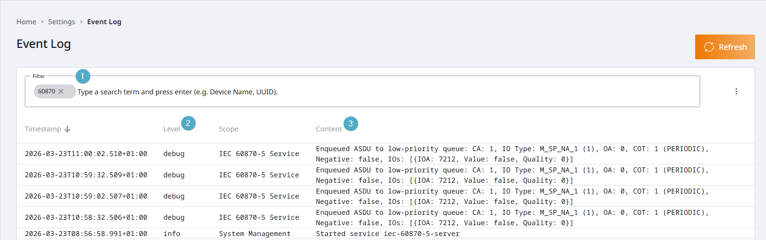
Filter: The event log can be filtered to
60870, as shown in the screenshot, so that only relevant events are displayed.Level: To display communication messages, the log level of the 60870-5 service must be set to
debugin the event log configuration.Content: Details regarding the transmission of the information object and the values transferred are displayed. The information shown depends on the IEC data type. In addition to the parameters already defined, the following parameters may also appear in the log:
OA (Origin Address): When updating measured values, the origin address is set to 0. When responding to commands, the origin address of the command is used.
Negative: Error bit for responses to commands.
0 = no error,1 = error. Errors may occur, for example, if the PLC is unreachable or returns an error.