Driver settings
Overview
The driver settings are used to parameterize a connection between PROCON-Connect and automation systems or field devices. This enables the exchange of data required for the visualization, control and monitoring of processes.
With PROCON-Connect, the collected data can be sent to an MQTT broker of a higher-level system via a connector, for example, or stored in a database for further analyses via a data logger.
Security
Warning
By default, no communication channels are open in PROCON-Connect, ensuring that the software complies with the requirements of various standards, such as the Cyber Resilience Act (CRA).
Fieldbus protocols such as Modbus and Allen-Bradley do not have built-in security mechanisms, so using them without additional security measures makes it impossible to ensure compliance with CRA or NIS 2.
If you use communication protocols or mechanisms that do not themselves provide the necessary security measures, these must be supplemented with administrative and organizational measures.
For more information, please refer to the Weidmüller Security Guideline.
Configure driver
The configurable drivers are listed in the overview. The drivers for OPC-UA and Modbus are always available. After licensing, the drivers for Codesys, Allen-Bradley or TIA can also be used.
Once a connection has been established, the connection can be used to import tags. This is carried out via the Tag overview.
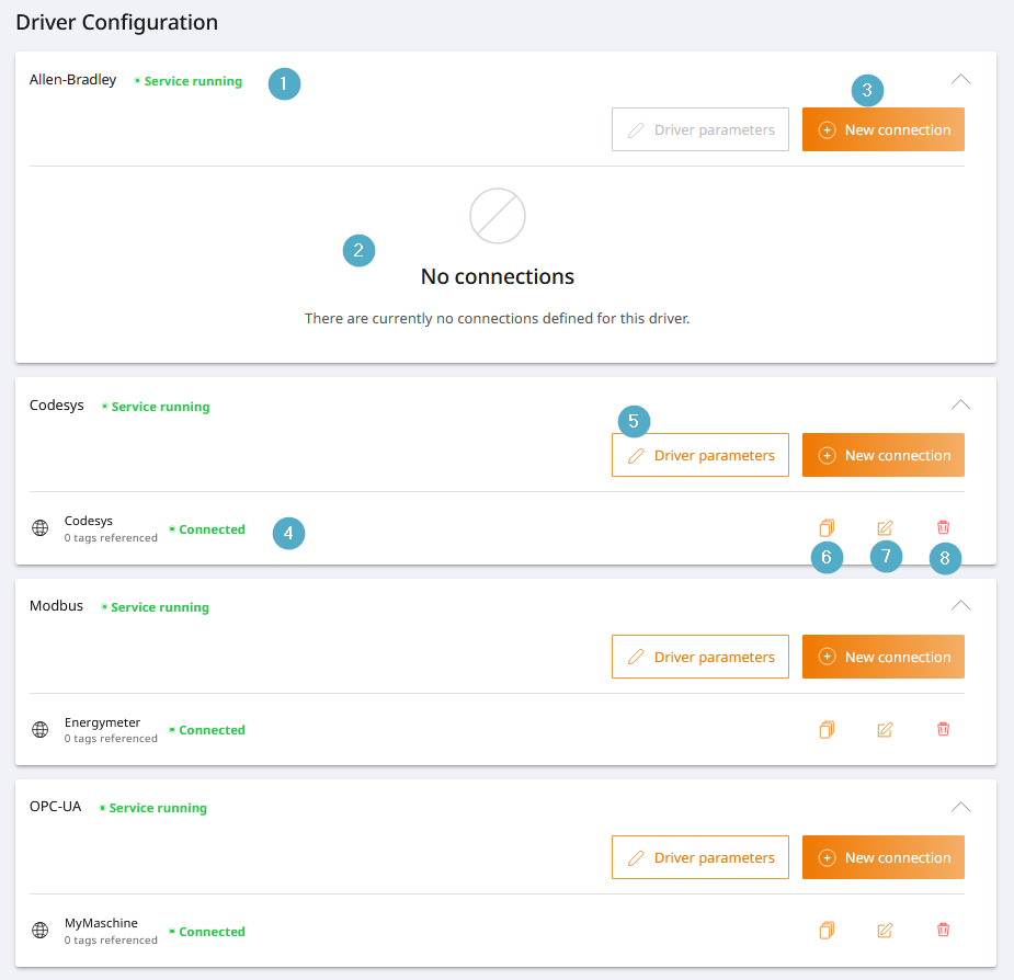
Driver name and licence: Name of the respective driver. The “Service active” status indicates that the driver service is running and a licence is available.
Connection overview: List of connections to this driver.
New connection: Creation of a new connection based on the respective driver.
Connection: Connection status: Connected (green), no connection (grey) or connection error (red) is displayed in colour.
Driver parameters: Driver parameters are global settings. They apply to all driver connections. They can be called up and edited. These parameters are driver-specific and differ between the individual drivers.
Duplicate connection: The selected connection is created again as a copy in order to be able to quickly create a large number of similar connections.
Edit connection: The selected connection can be edited.
Delete connection: Delete the connection. The deletion cannot be undone.
Allen-Bradley
Configuration parameters for establishing a connection to an Allen-Bradley controller.
The management of driver connections is the same for all drivers and is regulated in the section Configure driver.
Connection settings
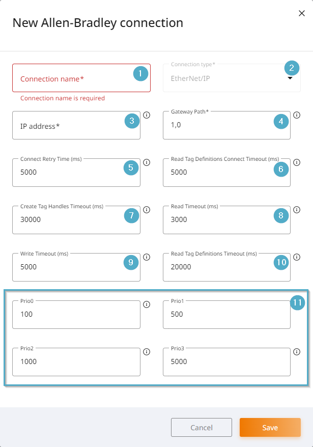
Connection name: The connection name must be unique. It is displayed in the driver overview.
Connection type: EtherNet/IP is currently preset and cannot be changed.
IP address: IP address or host name of the control unit.
Gateway Path: ControlLogix Gateway Path.
Connection attempt waiting time (ms): Time between connection attempts after a failed connection attempt.
Tag Definition Connect Read Timeout: Timeout time for reading tag definitions from the PLC when connecting.
Tag handle creation timeout (ms): Timeout time for creating the tag handles when connecting to the PLC.
Read timeout (ms): Timeout time for reading tags.
Write timeout (ms): Timeout time for writing tags.
Tag definition read timeout: Timeout time for reading tag definitions from the PLC when importing tag definitions.
Prio 0 to Prio 3: Update times in msec for variables with corresponding priority.
Timestamp
Timestamps for tags with Allen-Bradley connectivity are generated when the values are read into PROCON-Connect. The log itself does not provide timestamps.
Codesys
Configuration parameters for establishing a connection to a Codesys controller.
The management of driver connections is the same for all drivers and is regulated in the section Configure driver.
Driver parameters
Reconnect Time (s)
Default value
10 seconds
Function
Time in seconds between two connection attempts. Has an effect if the connection was lost or a connection attempt was unsuccessful.
Connection settings
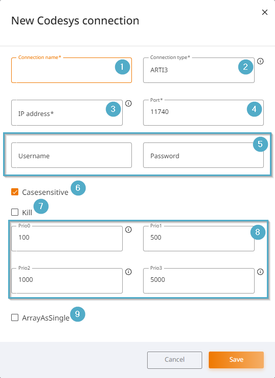
Connection name: The connection name must be unique. It is displayed in the driver overview.
Connection type: Selection between ARTI3/GATEWAY3/INI-FIle. ARTI3 is the standard for Codesys v3 on u-OS.
IP address: IP address or host name of the control unit.
Port: Port configuration for the connection. By default, Codesys communicates via port 11740.
Access data: Valid user name and password for coupling with the Codesys system.
Casesensitive: When activated, symbolic names are case-sensitive.
Kill: When activated, no real connection is established so that offline tests can be carried out.
Prio 0 to Prio 3: Update times in msec for variables with corresponding priority.
ArrayAsSingle: When activated, the individual array elements are read instead of reading an array in one piece.
Timestamp
Timestamps on tags connected to Codesys are generated when the values are read into the Codesys runtime. This timestamp is carried over unchanged when the values are read into PROCON-Connect.
Modbus TCP
Configuration parameters for establishing a connection to a Modbus device via TCP.
The management of driver connections is the same for all drivers and is regulated in the section Configure driver.
Driver parameters
Poll intervall (ms)
Default value
1000 ms
Function
Time interval between two value polls.
Modbus is not designed for high-frequency polling. A poll interval that is too short can lead to the following problems:
Overloading of the network or the serial connection. Collisions or timeouts can also occur with serial connections.
Requested devices must answer all requests, as a result of which they can switch to the busy or error status.
Some Modbus servers have a limit on the number of requests per second. If this is exceeded, the connection is terminated or further requests are ignored.
Each response must be processed on the polling side. With embedded devices, this can lead to high CPU utilization.
Connection settings
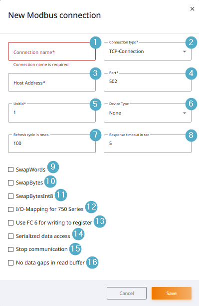
Connection name: The connection name must be unique. It is displayed in the driver overview.
Connection type: TCP (TCP/IP network) or RTU connection (serial interface) can be selected.
Host address: IP address or host name of the control unit.
Port: Port configuration for the connection. By default, Modbus TCP communicates via port 502.
Unitid: Unit ID/slave ID of the control unit. For special devices or for communication via Modbus gateways, otherwise irrelevant.
Device type: Dropdown for selecting an energy meter template. If a template is selected, tags contained in the template can be added directly to the tag list via the Tag-Import. Manual addressing of the registers is no longer necessary.
Refresh cycle (msec): Time span in milliseconds after which the complete required variable budget of a connection is updated.
Response timeout (s): Time period after which an error is reported due to communication interruption.
SwapWords: Modbus transmits data in 16-bit blocks (words) by default. For 32-bit data formats, two consecutive 16-bit words are combined. However, different devices or systems may interpret the order of these words differently. The SwapWords option can be used to reverse the order of the two 16-bit words.
SwapBytes: Modbus transmits data in 16-bit words (2 bytes), and depending on the device, these bytes can be stored or transmitted in a different order. The SwapBytes option is used to swap the order of the two bytes within a 16-bit word.
SwapBytesInt8: If this option is used, the two 8-bit values (bytes) within a 16-bit word are swapped.
I/O mapping for 750 Series: Special address calculation for communication with Wago 750 Series controllers.
Use FC 6 for writing to register: Function code 6 (WriteSingleRegister) is used instead of function code 16 (WriteMultipleRegisters). This can result in several write requests for certain data types.
Serialized data access: Activates the sequential processing of driver commands across all connections in which this function is activated. For each job, the connection is opened first, the read/write command is processed and then the connection is closed again. Used for older devices or gateways that can only handle one active connection.
Stop communication: This setting means that communication jobs for this connection are not forwarded by the driver and no driver error messages are generated for this connection.
No data gaps in read buffer: Some controllers do not allow general access to memory areas but only to memory areas that are occupied by tags. This parameter optimizes the read blocks so that only occupied memory areas are read. Affects Weidmüller M3000 or M4000, for example.
Timestamp
Timestamps for tags with a Modbus connection are generated when the values are read into PROCON-Connect. The log itself does not provide any timestamps.
Modbus RTU
Configuration parameters for establishing a connection to a Modbus device via serial interface.
The management of driver connections is the same for all drivers and is regulated in the section Configure driver.
Driver parameters
Default value
1000 ms
Function
Time interval between two value polls.
Modbus is not designed for high-frequency polling. A poll interval that is too short can lead to the following problems:
Overloading of the network or the serial connection. Collisions or timeouts can also occur with serial connections.
Requested devices must answer all requests, as a result of which they can switch to the busy or error status.
Some Modbus servers have a limit on the number of requests per second. If this is exceeded, the connection is terminated or further requests are ignored.
Each response must be processed on the polling side. With embedded devices, this can lead to high CPU utilization.
Poll intervall (ms)
Connection settings
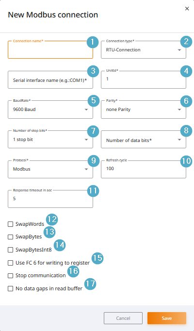
Connection name: The connection name must be unique. It is displayed in the driver overview.
Connection type: TCP (TCP/IP network) or RTU connection (serial interface) can be selected.
Serial interface name: Name of the serial interface via which communication is to take place, e.g. COM1, COM2, etc.
Unitid: Unit ID/slave ID of the control unit. For special devices or for communication via Modbus gateways, otherwise irrelevant.
BaudRate: Transmission speed in bits/second for serial communication.
Parity: Parity is used to detect single-bit errors during transmission. If a bit is corrupted during transmission, this is detected by the parity check and an error can be triggered, which in turn can lead to a retransmission.
Number of stop bits: Stop bits are additional bits that are transmitted at the end of a data packet to mark the end of a character and indicate to the recipient that the transmission is complete and that he can start processing the data. They are used for synchronization and ensure that the receiver recognizes the correct time to accept the next message.
Number of data bits: Number of bits used to represent a single data byte (or character). These data bits are the actual information part of the message that is transmitted between the devices.
Protocol: Select the protocol variant, e.g. JBus.
Refresh cycle (msec): Time span in milliseconds after which the complete required variable budget of a connection is updated.
Response timeout in sec: Time period in seconds after which an error is reported due to communication interruption.
SwapWords: Modbus transmits data in 16-bit blocks (words) by default. For 32-bit data formats, two consecutive 16-bit words are combined. However, different devices or systems may interpret the order of these words differently. The SwapWords option can be used to reverse the order of the two 16-bit words.
SwapBytes: Modbus transmits data in 16-bit words (2 bytes), and depending on the device, these bytes can be stored or transmitted in a different order. The SwapBytes option is used to swap the order of the two bytes within a 16-bit word.
SwapBytesInt8: If this option is used, the two 8-bit values (bytes) within a 16-bit word are swapped.
Use FC 6 for writing to register: Function code 6 (WriteSingleRegister) is used instead of function code 16 (WriteMultipleRegisters). This can result in several write requests for certain data types.
Stop communication: This setting means that communication jobs for this connection are not forwarded by the driver and no driver error messages are generated for this connection.
No data gaps in read buffer: Some controllers do not allow general access to memory areas but only to memory areas that are occupied by tags. This parameter optimizes the read blocks so that only occupied memory areas are read. Affects Weidmüller M3000 or M4000, for example.
Timestamp
Timestamps for tags with a Modbus connection are generated when the values are read into PROCON-Connect. The log itself does not provide any timestamps.
OPC-UA
Configuration parameters for establishing a connection to an OPC UA server.
The management of driver connections is the same for all drivers and is regulated in the section Configure driver.
Driver parameters
Kill variable name
Default value
KILL
Function
This variable is used to end or resume communication with the PLC.
How to configure?
The name of the kill variable is stored as the driver parameter, e.g. KILL.
The name of the kill variable can then be attached to any number of Boolean tags of this driver. To do this, first open the tag editor of the desired tag via the tag list. Fill the Name field with the kill variable, e.g. KILL.
If one of the tags configured in this way is TRUE or FALSE, all tags of the same driver connection with the same name (e.g. KILL) are set to the same value. This enables synchronous orchestration of the connection across multiple tags.
Status variable name
Default value
STATUS
Function
This variable is used to display the current status of a process or system.
How to configure?
The name of the status variable is stored as a driver parameter, e.g. STATUS.
The name of the status variable can then be attached to any number of tags of this driver. To do this, first open the tag editor of the desired tag via the tag list. Fill the Name field with the status variable, e.g. STATUS.
URL variable name
Default value
URL
Function
This variable contains the OPC UA server URL to which the driver should connect.
The software reads this variable to dynamically decide which OPC UA server it should connect to.
How to configure?
The name of the URL variable is stored as the driver parameter, e.g. URL.
The name of the URL variable can then be attached to any number of tags of this driver. To do this, first open the tag editor of the desired tag via the tag list. Fill the Name field with the URL variable, e.g. URL.
Connection settings
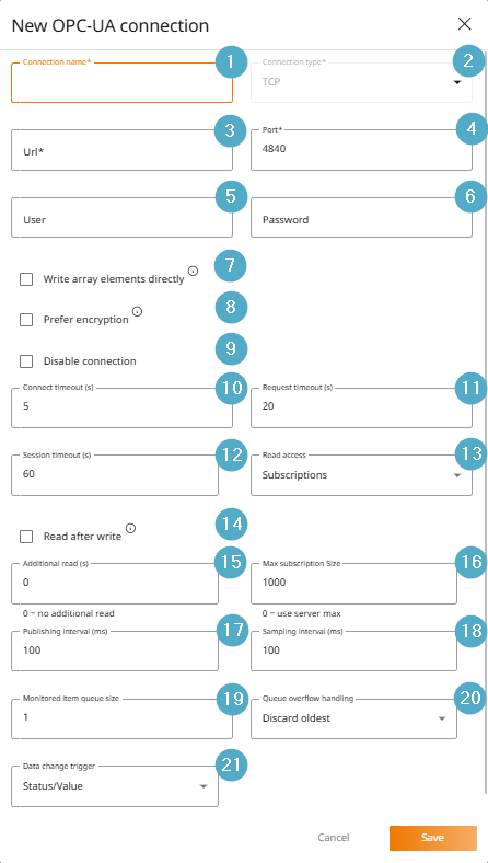
Connection name: The connection name must be unique. It is displayed in the driver overview.
Connection type: TCP connection is currently preset.
URL: IP address or host name of the OPC UA server. The prefix opc.tcp:// is always prepended.
Port: Port of the OPC UA server. The default is port 4840. The separation of URL and Port was implemented retrospectively. Older configurations that still have the port in the URL field according to the pattern [URL]:[Port] can continue to be used without modification.
User name: User name of the user on the OPC UA server to be used for pairing. Pairing with login details is optional.
Password: Password of the user on the OPC UA server to be used for pairing. Pairing with login credentials is optional.
Write array elements individually: Write values to exact array positions instead of reading, modifying and writing back the entire array. Not supported by every server.
Prefer encryption: If not activated, endpoints with the security policy NONE are preferred.
Deactivate connection: Created connection can be temporarily deactivated.
Connect timeout (s): Timeout for the connection process.
Request timeout (s): Timeout for requests.
Session timeout (s): Session timeout. The actual value may be different if the server does not support the set timeout.
Read mode: Selection between cyclical reading and subscriptions (reading on value changes).
Read after write: After each write operation, active reading is performed again with a time delay. This option should only be enabled if high-frequency changes are not detected by the OPC UA server. The additional reading means additional performance load. Before enabling this option, you should check whether the configuration can be resolved at the application level.
Additional read (s): Performs a manual read of variables every n seconds in addition to the subscription.
Max. Subscription size: Maximum number of monitored items per subscription. If more variables are requested, several subscriptions are used.
Publishing interval (ms): Desired subscription publishing interval. The actual value may be smaller if the server does not support the desired value.
Sampling interval (ms): Desired sampling interval of the monitored items. The actual value may be greater if the server does not support the desired value.
Monitored Item Queue Size: Specifies how many value changes for a monitored item (e.g. a sensor value or a variable) should be saved in a queue before they are sent to the client.
Queue overflow handling: Specifies which value is to be discarded if the monitored item queue overflows.
Data Change Trigger: Specifies the condition under which a value change is to be notified. Subscribing to timestamps is not supported by every server.
Timestamp
Timestamps on tags with OPC UA connectivity are obtained from the OPC UA server. The source of the timestamp may depend on the configuration of the OPC UA server.
TIA V2
Configuration parameters for establishing a connection to TIA Portal. The suffix V2 represents an internal differentiation from the previous driver within PROCON-WEB (SCADA).
The management of driver connections is the same for all drivers and is regulated in the section Configure driver.
Supported PLCs
The following PLCs and versions are supported:
PLC Family |
Firmware |
|---|---|
S7-1200 |
from 2.2 |
S7-1500, S7-1500P |
from 1.0 to 3.x |
S7-1500 Software Controller S7-1505S |
1.8 |
S7-1500 Software Controller S7-1507S |
2.0, 2.6, from 20.x |
S7-1500 Software Controller S7-1505SP |
2.0, 2.6, from 20.x |
virtueller Controller SIMATIC S7-PLCSIM Advanced |
from 2.0 |
Driver parameters
Kill variable name
Default value
KILL
Function
This variable is used to end or resume communication with the PLC.
How to configure?
The name of the kill variable is stored as the driver parameter, e.g. KILL.
The name of the kill variable can then be attached to any number of Boolean tags of this driver. To do this, first open the tag editor of the desired tag via the tag list. Fill the Name field with the kill variable, e.g. KILL.
If one of the tags configured in this way is TRUE or FALSE, all tags of the same driver connection with the same name (e.g. KILL) are set to the same value. This enables synchronous orchestration of the connection across multiple tags.
Status variable name
Default value
STATUS
Function
This variable is used to display the current status of a process or system.
How to configure?
The name of the status variable is stored as a driver parameter, e.g. STATUS.
The name of the status variable can then be attached to any number of tags of this driver. To do this, first open the tag editor of the desired tag via the tag list. Fill the Name field with the status variable, e.g. STATUS.
Connection settings
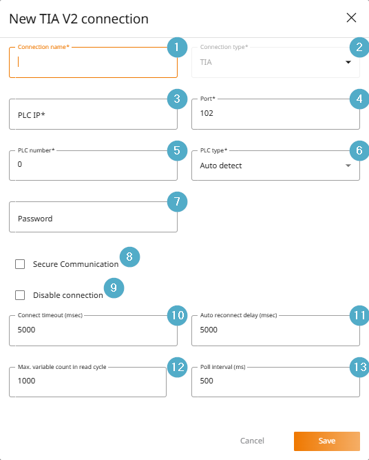
Connection name: The connection name must be unique. It is displayed in the driver overview.
Connection type: TIA preset and cannot be changed.
PLC IP: IP address of the PLC.
Port: Port 102 is used for communication by default and is preset.
PLC number: Number for logical mapping to virtual PLC number for controllers on the Profibus.
PLC type: Automatic detection is preset. However, if problems arise during detection, a specific type, e.g., S7-1500, can also be selected from the drop-down menu.
Password: If a password has been assigned in the TIA project, it must be entered here. If the TIA project does not use a password, the field can be left blank.
The password is stored in the TIA Portal as follows:
Device View–>Properties–>Protection and Security–>Access Authorization–>PasswordSecure communication: Allows the security function to be activated for encrypted and authenticated communication with the controller.
Requirements for secure communication:
CPU firmware supports secure communication
Secure connection enabled in TIA Portal:
Device View–>Properties–>Protection and Security–>Communication–>Enable Secure Connection
Disable connection: With this setting, communication requests for this connection are not forwarded by the driver and no driver error messages are generated for this connection.
Connection timeout (ms): Specifies how long to wait for a response from the controller during a connection attempt before the connection attempt is considered failed.
Automatic connection establishment after (ms): Specifies the time in milliseconds (ms) after which the system automatically attempts to reestablish a connection to the controller after the connection has been interrupted.
Maximum number of variables in the read cycle: Determines how many tags are queried simultaneously by the controller in a single read operation. The value should be reduced if the communication load of the controller is heavily utilized.
The configuration of the Siemens controller has a significant influence. The default value of 50% reservation for communication load should be adhered to, as otherwise the read time increases exponentially. The communication load is configured in the TIA Portal here:
Device view–>Properties–>Communication load.Poll Interval (ms): Determines how often the query for current data is performed.
The shorter the interval, the faster the response to process changes, but also the greater the load on the control system and the higher the risk in the event of a weak network connection.
The longer the interval, the lower the network load and CPU load, and the more stable the behavior during slow communication, but the slower the response time, e.g., in an HMI.
Timestamp
Timestamps for tags with a TIA v2 connection are generated when the values are imported into PROCON-Connect. The log itself does not provide timestamps.
Known issues
Firmware bug in Siemens 1500 CPUs with firmware 4.0: Frequent connection and disconnection with the PLC visible in the event log. Fix via firmware update from v4.0.4 brings improvement, but does not completely resolve the issue. Further information can be found in the Siemens Release Notes <https://support.industry.siemens.com/cs/document/109478459/firmware-update-s7-1500-cpus-incl-displays-and-et-200-cpus-(et-200sp-et-200pro)?dti=0& lc=en-DE>`_. Therefore, not currently approved for firmware v4.x.
The TIA V2 driver does not currently support importing fields from structures. Instead, the driver creates an element for each index.
Error codes
Error code |
Error text |
|---|---|
0x00000000 |
No error |
0x00000001 |
No error, job still in process |
0xFFF00000 |
Function not implemented |
0xFFF00001 |
Parameter error when calling function |
0xFFF00002 |
Invalid device number |
0xFFF00003 |
Invalid PLC number |
0xFFF00004 |
Invalid parameter type |
0xFFF00005 |
Insufficient memory |
0xFFF00006 |
Device already opened |
0xFFF00007 |
Device not opened |
0xFFF00008 |
Job removed |
0xFFF00009 |
Invalid job number |
0xFFF0000A |
Function not supported |
0xFFF0000B |
Adapter not initialized |
0xFFF0000C |
No free connections available |
0xFFF0000D |
Device not configured or not supported |
0xFFF0000E |
Hardware not found |
0xFFF0000F |
Error when reading parameters |
0xFFF00010 |
Error when writing parameters |
0xFFF00011 |
Demo period expired |
0xFFF00012 |
Wrong character in text. Conversion not possible |
0xFFF00013 |
Buffer is not long enough |
0xFFF00014 |
File not found |
0xFFF00015 |
Error when calling configuration program |
0xFFF00016 |
Error when loading DLL dynamically |
0xFFF00017 |
Could not create file |
0xFFF00018 |
Notification type already in use |
0xFFF00019 |
Running job already removed |
0xFFF0001A |
Job already removed |
0xFFF0001B |
Error when reading WLD file |
0xFFF0001C |
Error when writing WLD file |
0xFFF0001D |
Invalid structure in WLD file |
0xFFF0001E |
Multiple blocks in WLD file |
0xFFF0001F |
Function is not reentrant |
0xFFF00020 |
Function removed for code size reduction |
0xFFF00021 |
Because of parameter changes (in the moment) not applicable |
0xFFF00022 |
Invalid handle |
0xFFF00023 |
Invalid device type |
0xFFF50000 |
No free job buffer available |
0xFFF50001 |
Invalid packet |
0xFFF50002 |
No connection to PLC |
0xFFF50003 |
Connection closed |
0xFFF50004 |
Timeout |
0xFFF50005 |
Invalid context |
0xFFF50006 |
PLC memory error |
0xFFF50007 |
Invalid operating state |
0xFFF50008 |
Invalid address on PLC |
0xFFF50009 |
Invalid mode |
0xFFF5000A |
No data available e.g. DB is missing |
0xFFF5000B |
Priority class associated to OB does not exist |
0xFFF5000C |
Empty blocklist |
0xFFF5000D |
Block size error |
0xFFF5000E |
Invalid block number |
0xFFF5000F |
Protection level of function not sufficient |
0xFFF50010 |
Unknown SSL-ID (e.g. access to CP instead of PLC) |
0xFFF50011 |
Unknown SSL-index (e.g. access to CP instead of PLC) |
0xFFF50012 |
Information currently not ascertainable |
0xFFF50013 |
Unknown error message from PLC (please report!) |
0xFFF50014 |
Hardware error e.g. not available periphery |
0xFFF50015 |
Object access not allowed |
0xFFF50016 |
Context not supported |
0xFFF50017 |
Type (data type) not supported |
0xFFF50018 |
Internal error, please report |
0xFFF50019 |
Error rebooting PLC |
0xFFF5001A |
Error restarting PLC |
0xFFF5001B |
Connection end received |
0xFFF5001C |
PLC not found |
0xFFF5001D |
Too many data for this version of ACCON-AGLink |
0xFFF5001E |
PLC does not support this function |
0xFFF5001F |
Wrong Password |
0xFFF50020 |
Connection already legitimated |
0xFFF50021 |
Legitimation already released |
0xFFF50022 |
Password not neccessary |
0xFFF50023 |
At least one variable address invalid |
0xFFF50024 |
Job does not exist |
0xFFF50025 |
Invalid job state |
0xFFF50026 |
Invalid cycle time |
0xFFF50027 |
No more cyclic job possible |
0xFFF50028 |
Function not posible for this job (invalid state) |
0xFFF50029 |
Function abort (overload) |
0xFFF5002A |
No data for this variable |
0xFFF5002B |
Wrong time format |
0xFFF5002C |
Unknown PI name |
0xFFF5002D |
File transfer canceled by NCK |
0xFFF5002E |
Response too large for PDU size |
0xFFF5002F |
No H-PLC found |
0xFFF50030 |
Data not changed |
0xFFF50031 |
Received data is corrupt |
0xFFF50032 |
The requested parameter has the wrong size or type |
0xFFF50033 |
The parameter has a wrong value |
0xFFF50034 |
The parameter is not changeable |
0xFFF50035 |
The parameter is read only |
0xFFF50036 |
The variable definition contains the wrong size |
0xFFF50037 |
Array index does not exist |
0xFFF50038 |
PARA does not exist |
0xFFF50039 |
Error during disconnect |
0xFFF5003A |
Transfer and execute to NCK was aborted |
0xFFF5003B |
Invalid variable request set |
0xFFF5003C |
SSL library not found |
0xFFF5003D |
SSL library not loaded |
0xFFF5003E |
Not all SSL functions found |
0xFFF5003F |
Libcrypto not loaded |
0xFFF50040 |
Not all crypto functions found |
0xFFF50041 |
Invalid SSL version found |
0xFFF50042 |
Could not initialize SSL |
0xFFF50043 |
No secure communication |
0xFFF50044 |
Only secure communication |
0xFFF50045 |
Error opening DER file |
0xFFF50046 |
Error reading DER file |
0xFFF50047 |
Error opening PEM file |
0xFFF50048 |
Error reading PEM file |
0xFFF50049 |
Error not a valid buffer |
0xFFF5004A |
error in certificate store |
0xFFF5004B |
Error untrusted certificate |
0xFFF5004C |
Error SSL not supported on this OS |
0xFFF5004D |
Error SSL was already deleted |
0xFFF30000 |
Error when reading device information |
0xFFF30001 |
Error when reading bus parameters |
0xFFF30002 |
Error when writing bus parameters |
0xFFF30003 |
No resources available on device |
0xFFF30004 |
Invalid device |
0xFFF30005 |
Adapter not found |
0xFFF30006 |
Needed device driver not found |
0xFFF40000 |
Error in layer4 |
0xFFF40001 |
No send buffers available |
0xFFF20000 |
The desired adapter address already exists |
0xFFF20001 |
Invalid HSA (smaller than biggest active participant) |
0xFFF20002 |
Adapter is not in the logical ring |
0xFFF20004 |
Received package has wrong content |
0xFFF20006 |
Unknown error number from adapter |
0xFFF20007 |
Unknown error number from device driver |
0xFFF20008 |
Communications adapter has been removed |
0xFFF20009 |
Modem has been removed |
0xFFF2000A |
No directly connected PLC found |
0xFFF2000B |
Setting a socket option failed |
0xFFF20313 |
Invalid speed on MPI bus |
0xFFF20314 |
Address is bigger than HSA |
0xFFF20315 |
The desired adapter address already exists |
0xFFF2031A |
No other active bus participants found |
0xFFF2031C |
Bus is jammed |
0xFFF2031D |
Bus is jammed |
0xFFF2031E |
Automatic detection of bus profile doesn’t work, missing bus parameter telegram |
0xFFF20337 |
Legitimation missing |
0xFFF24000 |
PCAP library not found |
0xFFF24001 |
PCAP function in library not found |
0xFFF24002 |
No PCAP adapter found |
0xFFF24003 |
Specified PCAP adapter not found |
0xFFF24004 |
Error compiling filter expression |
0xFFF24005 |
Error setting filter expression |
0xFFF24006 |
Error in pcap_open_live |
0xFFF24007 |
Error in pcap_sendpacket |
0xFFF24008 |
Error in pcap_dispatch |
0xFFF24009 |
Error in pcap_next_ex |
0xFFF2400A |
Required helper library not found |
0xFFF2400B |
Helper library function not found |
0xFFF2400C |
Error in helper library function call |
0xFFF2400D |
Not enough memory |
0xFFF2400E |
You selected not supported adapter hardware |
0xFFF10000 |
COM-Port already used |
0xFFF10001 |
Modem not found |
0xFFF10002 |
Modem not onhook |
0xFFF10003 |
Modem not offhook |
0xFFF10004 |
Error in basic initialisation |
0xFFF10005 |
Error in Initstring 1 |
0xFFF10006 |
Error in Initstring 2 |
0xFFF10007 |
Error in Initstring 3 |
0xFFF10008 |
Error in Initstring 4 |
0xFFF10009 |
Error in dialtype sequence |
0xFFF1000A |
Error in dialtone sequence |
0xFFF1000B |
Error in autoanswer sequence |
0xFFF1000C |
Modem has been removed |
0xFFF1000D |
Connection could not be established |
0xFFF1000E |
Login denied. Unknown user. |
0xFFF1000F |
Login denied. Wrong password. |
0xFFF10010 |
Login denied. Callback number defined in adapter. |
0xFFF10011 |
Error while dialing |
0xFFF80000 |
Function not allowed |
0xFFF80001 |
Invalid project handle |
0xFFF80002 |
Error opening project |
0xFFF80003 |
Error creating program instance of project |
0xFFF80004 |
Error closing project |
0xFFF80005 |
No resp. no more programs found |
0xFFF80006 |
Program not found |
0xFFF80007 |
At least one of the specified parameters is invalid |
0xFFF80008 |
Runtime has expired (demo version) |
0xFFF8000A |
No resp. invalid data specified |
0xFFF8000B |
The program selected has no symbol table |
0xFFF8000C |
Symbol table already opened |
0xFFF8000D |
No resp. no more symbol entry found |
0xFFF8000E |
Error reading symbol entry |
0xFFF8000F |
Symbol not found |
0xFFF80010 |
Operand not found |
0xFFF80011 |
Invalid symbol |
0xFFF80012 |
Invalid operand |
0xFFF80013 |
Invalid filter string |
0xFFF80014 |
Data block (DB) not present |
0xFFF80015 |
Error reading DB block data |
0xFFF80016 |
Error parsing DB block data |
0xFFF80017 |
An opened DB is already present |
0xFFF80018 |
No opened DB present |
0xFFF80019 |
No resp. no more DB component found |
0xFFF8001A |
Specified DB component not found |
0xFFF8001B |
Specified DB component is invalid |
0xFFF8001C |
Specified DB component not matching |
0xFFF8001E |
Invalid constant |
0xFFF8001F |
Invalid constant size or format |
0xFFF80020 |
Object type initialization failed |
0xFFF80021 |
Invalid version of message configuration |
0xFFF80022 |
Error opening message configuration |
0xFFF80023 |
Error closing message configuration |
0xFFF80024 |
No resp. no more message entry found |
0xFFF80025 |
No resp. no more language found |
0xFFF80026 |
Database access error |
0xFFF80027 |
Invalid signal number |
0xFFF80028 |
Invalid add. value specification |
0xFFF80029 |
Add. value number invalid |
0xFFF8002A |
Element type of add. value invalid |
0xFFF8002B |
Add. value data length invalid |
0xFFF8002C |
Format specification missing |
0xFFF8002D |
Format specification invalid |
0xFFF8002E |
No resp. no more text library found |
0xFFF8002F |
No resp. no more text library entry found |
0xFFF80030 |
Not enough memory |
0xFFF80031 |
Block type invalid |
0xFFF80032 |
Listing handle invalid |
0xFFF80033 |
Block not present |
0xFFF80034 |
Error reading block data |
0xFFF80035 |
Error parsing block data |
0xFFF80036 |
No resp. no more declaration found |
0xFFF80037 |
No resp. no more attributes found |
0xFFF80038 |
Writing CPU list failed |
0xFFF90000 |
Read error |
0xFFF90001 |
Write error |
0xFFF90002 |
Read error (variable content, type) |
0xFFF90003 |
Wrong PLC type |
0xFFF90064 |
Internal assert wrong |
0xFFFA0000 |
Not applicable |
0xFFFA0001 |
Access invalid element |
0xFFFA0002 |
Access buffer too small |
0xFFFA0003 |
Access buffer invalid S5TIME value |
0xFFFA0004 |
Access buffer invalid S5TIME base |
0xFFFA0005 |
Access buffer invalid S7 COUNTER value |
0xFFFA0006 |
Path missing expanded index |
0xFFFA0007 |
Path invalid |
0xFFFA0008 |
Path end reached |
0xFFFA0009 |
Path unknown field |
0xFFFA000A |
Unknown child |
0xFFFA000B |
Array is no value type |
0xFFFA000C |
Array index missing |
0xFFFA000D |
Array index invalid |
0xFFFA000E |
Array index not allowed |
0xFFFA000F |
Array range not allowed |
0xFFFA0010 |
Array range invalid |
0xFFFA0011 |
UDT has no base type |
0xFFFA0012 |
Unknown error code |
0xFFFA0013 |
Wrong symbol ID |
0xFFFA0014 |
Item access denied |
0xFFFA0015 |
Read only item |
0xFFFA0016 |
Partial errors |
0xFFFA0017 |
Not an instance |
0xFFFA0018 |
Wrong symbol ID path |
0xFFFA0019 |
Symbolic wrong area |
0xFFFA001A |
Wrong value range |
0xFFFA001B |
PLC cant deliver |
0xFFFA001C |
PLC object does not exists |
0xFFFA001D |
PLC type info missing |
0xFFFA0050 |
Invalid datablock |
0xFFFA0051 |
Datablock is optimized |
0xFFFA0052 |
Invalid Tag |
0xFFFA0053 |
Start address too big |
0xFFFA0054 |
Not allowed symbolic access |
0xFFFA006E |
File read error |
0xFFFA0074 |
Project file not found |
0xFFFA0075 |
Project file unsupported extension |
0xFFFA0076 |
Project folder missing |
0xFFFA00FD |
Invalid agl version |
0xFFFA00FE |
Invalid filter |
0xFFFA00FF |
Invalid node |
0xFFFA0100 |
Invalid flags |
0xFFFA0101 |
Invalid alarm ID |
0xFFFA0102 |
Invalid alarm LCID |
0xFFFA0103 |
No alarms found |
0xFFFA0104 |
Invalid alarmtext |
0xFFFA0105 |
Invalid alarmtext index |
0xFFFA0106 |
Invalid LCID |
0xFFFA0107 |
DB not found |
0xFFFA0108 |
No alarm subscription active |
0xFFFA0109 |
Already open |
0xFFFA010A |
Not open |
0xFFFA010B |
Must be word aligned |
0xFFFA010C |
Password required |
0xFFFA010D |
Parameter is null |
0xFFFA010E |
Parameter is zero |
0xFFFA010F |
Invalid handle |
0xFFFA0110 |
Root handle expected |
0xFFFA0111 |
Result buffer too small |
0xFFFA0112 |
NCK BTSS item invalid |
0xFFFA0113 |
NCK BTSS item unknown |
0xFFFA0114 |
NCK BTSS item not supported in selected CNC version |
0xFFFA0115 |
Alarm subscription is already active |
0xFFFA0190 |
Internal communication error |
0xFFFA0191 |
Internal communication error 0 |
0xFFFA0193 |
Internal communication error 2 |
0xFFFA0194 |
Write bool range needs modulo 8 start and count |
0xFFFA0195 |
Wrong read type |
0xFFFA0196 |
PLC auto detect failed |
0xFFFA0197 |
Only single values allowed |