Process coupling
The process coupling component is used to configure the database and its communication with the control system. In the runtime, this is carried out via the TagServer, which has different plug-ins for communication using different protocols. Up to eight different driver plug-ins can be used in a project.
The drivers implemented in the plug-ins sometimes require specific equipment (fieldbus plug-in cards, COM interfaces …) and are not available for all server variants because these plug-ins are very specific to the operating system.
There are three different types of variables in PROCON-WEB:
Process variables |
Process variables |
Text variables |
|---|---|---|
|
|
TagString| |
State 0 or 1 |
Numerical values (internally as float) |
Strings |


All process variables are identified with a symbolic name, which is then known within the images, formulas, or other components of PROCON-WEB. These definitions are part of the project data and are used by all PROCON-WEB function groups. All program-internal data access is implemented using the symbolic name (or the index, assigned by the system). The driver assignment and the driver-specific information are only evaluated during communication with the process. PROCON-WEB is therefore a completely control-neutral HMI and SCADA system. The data exchange from the runtime system to the process takes place via the control-specific driver. If problems occur during communication with the controller (e.g., cable not plugged in, data not available, protocol error …), these are reported and displayed as system alarms by the runtime system. Each driver requires specific parameterisations and settings to be able to establish communication. This information is listed in the driver manual and must be considered during installation.
Configuration
Process communication
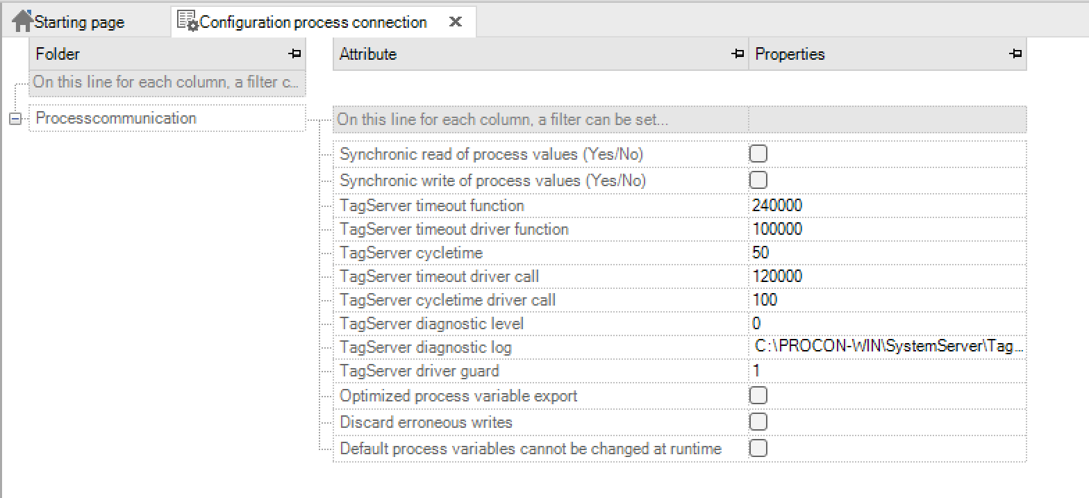
Note
The standard values of the configuration setting are selected so that they are suitable for 90% of the application cases.
Key name |
Input |
Meaning |
|---|---|---|
Synchronous reading of the process values (yes / no) |
Default value: no |
Specifies whether the process values should be read synchronously. |
Synchronous writing of the process values (yes / no) |
Default value: no |
Specifies whether the process values should be written synchronously. |
TagServer timeout function |
Default value: 240000 |
Specifies the duration in milliseconds until the synchronous TagServer function times out. |
TagServer timeout driver function |
Default value: 100000 |
Specifies the duration in milliseconds until the synchronous driver function in the TagServer times out. |
TagServer cycle time |
Default value: 50 |
Specifies the cycle time in milliseconds for synchronous calls in the TagServer. |
TagServer timeout driver call |
Default value: 120000 |
Specifies the duration in milliseconds until a driver call in the TagServer times out. |
TagServer cycle time driver call |
Default value: 100 |
Specifies the cycle time in milliseconds for executing driver calls. |
TagServer diagnostic level |
0… 5 Default value: 0 |
Sets the diagnostic level of the TagServer to the specified value. |
With 0, no diagnostic log is kept. |
||
TagServer diagnostic log |
Path with filename |
|
Default value: “C: PROCON-WEB Logs TagServer.log”. |
Path and name for the diagnostic protocol file. |
|
TagServer driver monitoring |
Default value: 1 |
Indicates whether the driver should be monitored. 0/1 means activated. 2 means deactivated. |
Optimised process variable export |
Default value: yes |
If active, only referenced process variables, i.e. those used in the project, are exported. |
Discard incorrect writing task |
Default value: no |
If active, incorrect writing tasks are discarded by the driver to the controller. This ensures that no old jobs are transferred, for example if the controller was offline or was changed |
Default process variable can be changed during runtime |
Default value: active |
Writing orders for default variables will be discarded |
Units
In the tree of the PROCON-WEB-Designer there is a new entry “Units” under “Process connection”. The units for numerical process variables can be defined here. Units are now divided into a “base” and a “conversion unit”. As previously known, the “base unit” can be given a name, the display unit and a description. A “base unit” can have several “conversion units”. These contain the display unit, a conversion formula and a description

This gives you the option of defining country-specific units that are also taken into account when switching languages.
Important
Currently, however, only a language change is carried out and no unit conversion! The texts themselves can no longer be configured in multiple languages!
Like almost every element in PROCON-WEB, units are defined in a grid.

In the picture you can see a “base unit” (mass_kg) and two “conversion units”.
The value for the display is calculated using the formula when the units are switched. The ‘x’ in the formula stands for the base value. The operations ‘+’, ‘-’, ‘/’, ‘*’ are allowed; brackets can also be used. Other characters are not allowed.

Right-click on “New conversion unit” to enter additional conversion units with the respective conversion formulas as well as the translation of the unit and a description.
A so-called unit set contains the “mapping” from “conversion unit” to “base unit”. Say with which formula the value will be calculated later when switching and which unit will be shown on the display. With the mappings, you can only ever add a “base unit” with a “conversion unit”.
Here is an example of a unit set “English” with the two “basic units” (distance and temperature) with their respective “conversion units” (i and K)

The unit for numeric process variables can be selected in the “Unit” column in the TagEditor. This can be displayed in the picture using a label control for the selected variable. The units can be switched in different ways.
Language A unit set can be assigned to a language. If the language is changed during runtime, the units that are defined in the set are switched / converted

System variable There is a system variable “__System_CurrentUnitSet“ which can be used to switch between units.
Selection dialog A function “Open unit selection dialog” can be placed on a button, for example. In the runtime, after pressing the button, a selection dialog for the possible unit sets for switching is displayed.
Decimal place shift A new column with the meaning “post-decimal place shift” has been inserted. Numerical values between -10 and 10 can be inserted. The entered value indicates by how many decimal places the converted unit should be shifted. Please note that the entered value is not the new number of decimal places but shifts the standard value.

Enums
General information
In the project tree in the “Process coupling” area there is an item “Enums”. In this, multilingual texts can be assigned to a numerical or logical variable. These are used in the logbook entry instead of the process variable value.
Definition of the enums
A name is given to an enum. Then enum elements can be created. These are given an index and a multilingual text.

Important
The index of the enum element must be unique.
Generated enums can then be assigned to a variable in the process variable list. The new column “Enum” has been added for this purpose. In this a selection dialog opens via the button.
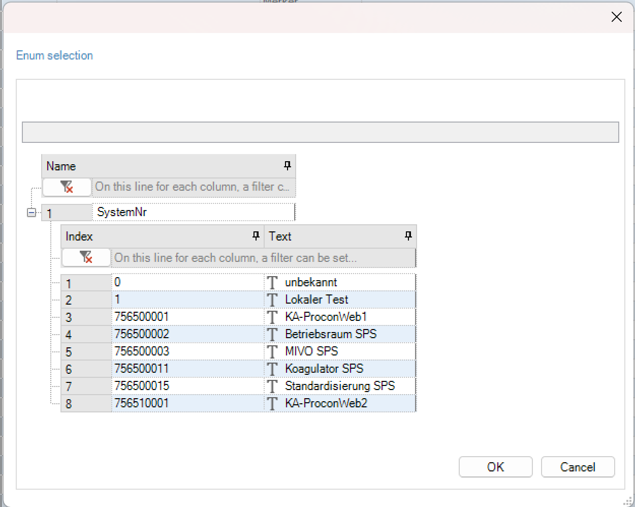
Important
There is an error text in the project that is used if the value of the process variable does not correspond to an enum value. This error text is created in the system dialogs and is called “Invalid enum value”
Process variables
General
The process variables to be used in the project are created in the process variable editor. A variable either has a process connection via a communication driver or is used as an auxiliary variable (marker) within the visualisation project.

Variable counting for licensing
For the licensing of PROCON-WEB, all process variables with driver coupling are counted by the system. Default-Variables are excluded. Text variables with driver coupling count as one data point regardless of their length. With numerical and logical process variable fields, each field index counts as one data point.
Working with process variables
Creation of process variables
In the process variable editor, the variables are created via the toolbar or via the context menu of the right mouse button in the work area. The procedure for creating the process tags is the same for each process tag type. Process variables can also be copied or duplicated. When inserting the process variable, the name is automatically incremented to avoid duplicate names.
Über das Kontextmenü ist es auch möglich, eine gefilterte Variablenliste oder eine selektierte Auswahl an Variablen zu exportieren.

The following table lists the meaning of the columns in the process variable editor.
Key |
Meaning |
|---|---|
Name |
Name of the process variable |
Maximum of 255 characters, must not contain any spaces or special characters; names longer than 32 characters will be shortened for the TagServer |
|
The name of the process variable must be unique and can only be defined once. |
|
Plant structure |
Name of the assigned plant structure |
Comment |
In the comment column, the user has the option of entering a comment for each process variable. Max. 255 characters can be assigned. The comment serves as an aid in the configuration and is only displayed in the designer. |
Display name |
A name can be specified here with which the variable is to be displayed at runtime (for example in the chart control). The display name helps the runtime user to operate, since the configured variable names are not necessarily readable for the runtime users or cannot be assigned. The display name is then used for this. Max. 255 characters can be assigned |
Display comment |
A comment can be entered here, which is displayed when the variable is mouse-over (for example in the chart control). Max. 255 characters can be assigned. |
Global |
Determines whether the variable is defined locally or globally. Global means that the variable has the same value everywhere and in every client. Local definition means each client has its own local copy of this. |
A variable with driver coupling is generally defined globally. |
|
[x] |
The field size indicates how many field elements XE “Field elements” with the same definition after this structural element. With a field size of 10, for example, 10 individual elements are obtained, but they all have the same minimum, maximum, default values, etc.They are addressed via the field index which is added to the variable name in square brackets, e.g. with Temp [3] the fourth field element. The last field element has the field index ‘field size - 1’. |
If you want to create a single variable, the field size must be set to ‘1’. The use of fields is useful, for example, for ASCII strings or tables. |
|
With string variables, max. 255 characters can be assigned, 9999 with numeric variables. |
|
0.x |
The number of decimal places for numeric process variables is specified here. A maximum of 10 characters are possible. |
MinPC |
Specifies the smallest value displayed in the runtime system. Maximum16 decimal places and 2 decimal places are possible. |
MaxPC |
Specifies the biggest value displayed in the runtime system. Maximum16 decimal places and 2 decimal places are possible. |
Min PLC |
Specifies the smallest value displayed in the PLC. Maximum16 decimal places and 2 decimal places are possible. |
Max PLC |
Specifies the largest value displayed in PLC. Maximum16 decimal places and 2 decimal places are possible. |
Important
For more information on the Min- / MaxSPS and Min- / MaxPC parameters and on standardisation, see Chapter processs coupling – value ranges.If no normalisation is necessary, only MinPC and MaxPC need to be defined. These details are then used identically for MinSPS and MaxSPS.
Key |
Meaning |
|---|---|
Default |
Indicates the value to which the process variable is set when the system is initialized |
Unit |
Reference to units in chapter process coupling (optional). Can only be selected for numeric variables. |
BaseTag |
Since indirect addressing for several clients is managed by the global TagServer in a client / server application, so that each client has its own control variable sets and its own indirectly addressed process variables, these must be marked as BaseTag in the process variable list. Thus, the global TagServer creates clones of the control variable sets and the indirectly addressed process variables for each configured client. |
Num. field |
Numeric field in which each letter of a text variable is stored as an ASCII value in one element. |
External |
If PROCON-WEB or the TagServer is to serve as an OPC UA server, the external access option is defined here. |
Driver |
Specifies the driver with which communication with the control system is implemented. |
I / O |
Indicates the type of process variable. Possible entries are |
BiDir: write and read size (preferred definition for setpoints) |
|
Input: read size (actual values) |
|
Output: write size (setpoints that cannot be read back) |
|
Driver-specific columns |
The following columns require driver-specific information that is necessary to transfer the process variable to the controller (e.g. data block no., No. of the data word, display format). This information depends on the respective driver and is therefore described in the corresponding driver manual. |
Marking unused process variables
With the option “Mark process variable without reference” the user can display all unreferenced process variables.

By deleting all selected variables or by selecting certain process variables, the user can carry out project optimisation.
Important
The variables filtered out by the interface are also selected and also deleted.
Important
To make the project database smaller after this optimisation, “File-> Reorganise database” must also be executed!
Tag value ranges
Two value ranges must be defined for each process variable in PROCON-WEB. On the one hand, these are important for the display and use of the process variables in the user interface, and on the other hand for communication with the PLC. Due to the different values of Min / MaxPC and Min / MaxSPS, a normalisation can also be mapped.
Possibilities of definition
Definition via Min / MaxPC and Min / MaxSPS The value range of a process variable can be defined in the PROCON-WEB process variable editor. The columns Min / MaxPC and Min / MaxSPS have the following meaning:
MinSPS |
Indicates the smallest valid value of the variable on the controller. |
|---|---|
MaxSPS |
Indicates the largest valid value of the variable on the controller. |
MinPC |
Specifies the smallest valid value that is displayed in the runtime system. |
MaxPC |
Specifies the largest valid value that is displayed in the runtime system. |

A normalisation can be configured by defining the parameters accordingly.
If normalisation is not required, the columns “MinSPS” and “MaxSPS” can also be hidden for a better overview. If the values in the columns “MinPC” and “MinSPS” as well as “MaxPC” and “MaxSPS” are the same, changing the column “MinPC” also changes the column “MinSPS”, and changing the column “MaxPC “Also changed the” MaxSPS “column.
Defined by the PLC import Via the PLC import, variable definitions can be imported directly from the PLC or the PLC program into PROCON-WEB. For some of the available imports, the value ranges are also imported correctly here.” “Unfortunately, for technical reasons, this is not possible with all drivers.One remedy here is to define another tag class as the basis for the import.

If neither the first nor the second mentioned option for defining the value range is successful during the PLC import, the values can also be adjusted by multiple changes.

Input limit of a number field: An input limit can be set on a number field that is used to change a process variable.

Definition of number field: The following options are available:
No input limit: With the “No input limit” option, the value range of the assigned process variables is used as the input range
Static input limit: If the option “Static input limit” is used, the user can specify constant values as the lower and upper input limit.
Dynamic input limit: The “dynamic input limit” uses numeric process variables as input limit values. The limit value of the lower and upper limit is determined by the value of the assigned numeric process variable.
Applications of the value ranges
General: Many of the dynamisations in PROCON-WEB can be defined as a “numerical area”. These dynamisations are, for example, colour changes or symbol changes. For this, it is extremely important for the runtime to know the value range of the variable to be able to carry out the change or colour change accordingly.
Symbol change: The symbol change is used to dynamically exchange symbols based on the value of a process variable. When the symbol is dynamised as “Area, Numeric”, the symbol switch is carried out via an area from the symbol list. The value range of the numerical process variables is mapped linearly on the symbol list in the runtime system.
Colour change: The colour change is used to dynamically change the colour of, for example, symbols or number fields based on the value of a process variable. When the object is dynamised as a “numerical range”, the value range of the process value is mapped linearly to the two specified colours. Depending on the sequence selected, the colour is changed in the runtime system.
Bar graph: The bar display is used to graphically display process values. Depending on the configuration of the bar, the minimum or maximum value means a full scale of the bar. The size of the bar for values in between is calculated using the value range of the process variable.
Under / over range: A range of values for the process variables is specified in the process variable definition. If this value is undershot (variable value less than minimum value) or exceeded (variable value greater than maximum value), this is indicated accordingly in the display of the variable in the user interface.
Since the value range should not normally be exceeded or fallen below, conclusions can be drawn about faults in the system, e.g. a defective sensor.
Normalisation in the runtime
Reading access: With reading access, the standardisation takes place using the following formula:Range = HighPC - LowPC;Limit = HighSPS - LowSPS;Result = LowPC + Range / Limit * (Incomming - LowSPS);
Writing access: With writing access, the standardisation is carried out using the following formula:Range = HighPC - LowPC;Limit = HighSPS - LowSPS;Result = LowSPS + Limit / Range * (Outgoing - LowPC);
Tag-Properties
With the help of these tag properties, further properties of the process variables can be defined or changed during runtime. By default, every tag, whether logical, numeric or string, has the following new properties:
Num. 1 (numeric)
Num. 2 (numeric)
Num. 3 (numeric)
Num. 4 (numeric)
Bool 1 (logical)
Bool 2 (logical)
String 1 (String)
String 2 (String)
The name of the new properties and partly also their parameters can be changed via the context menu or dialog, whereby this applies not only to one day, but to the entire column:
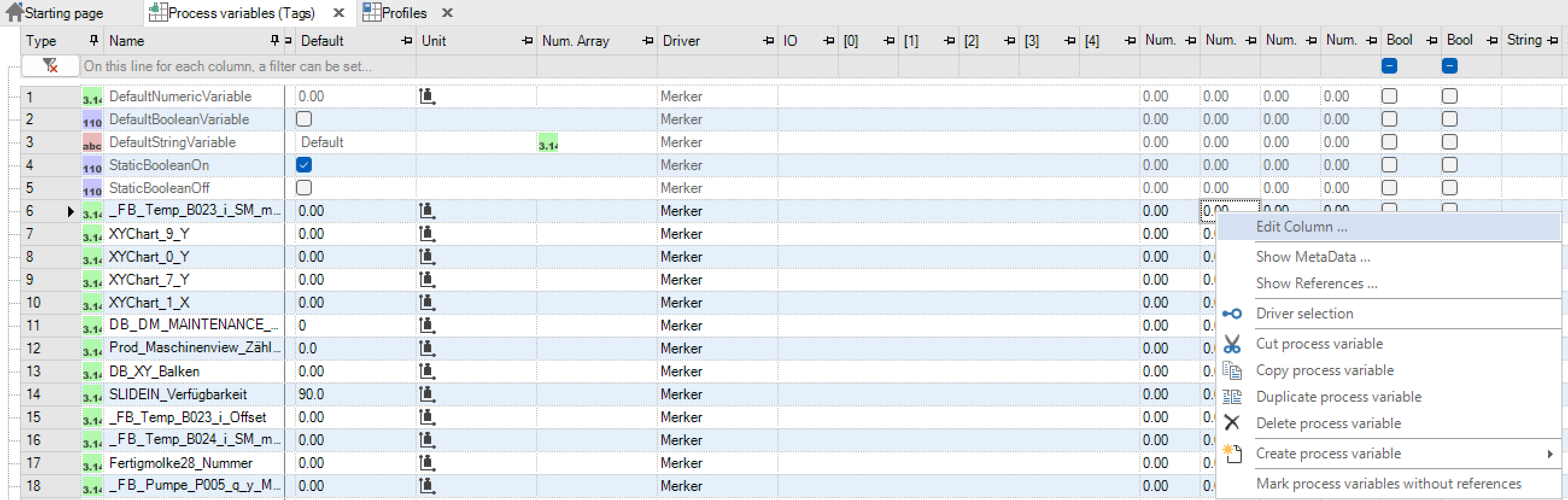
A dialog opens in which the parameters can be changed:
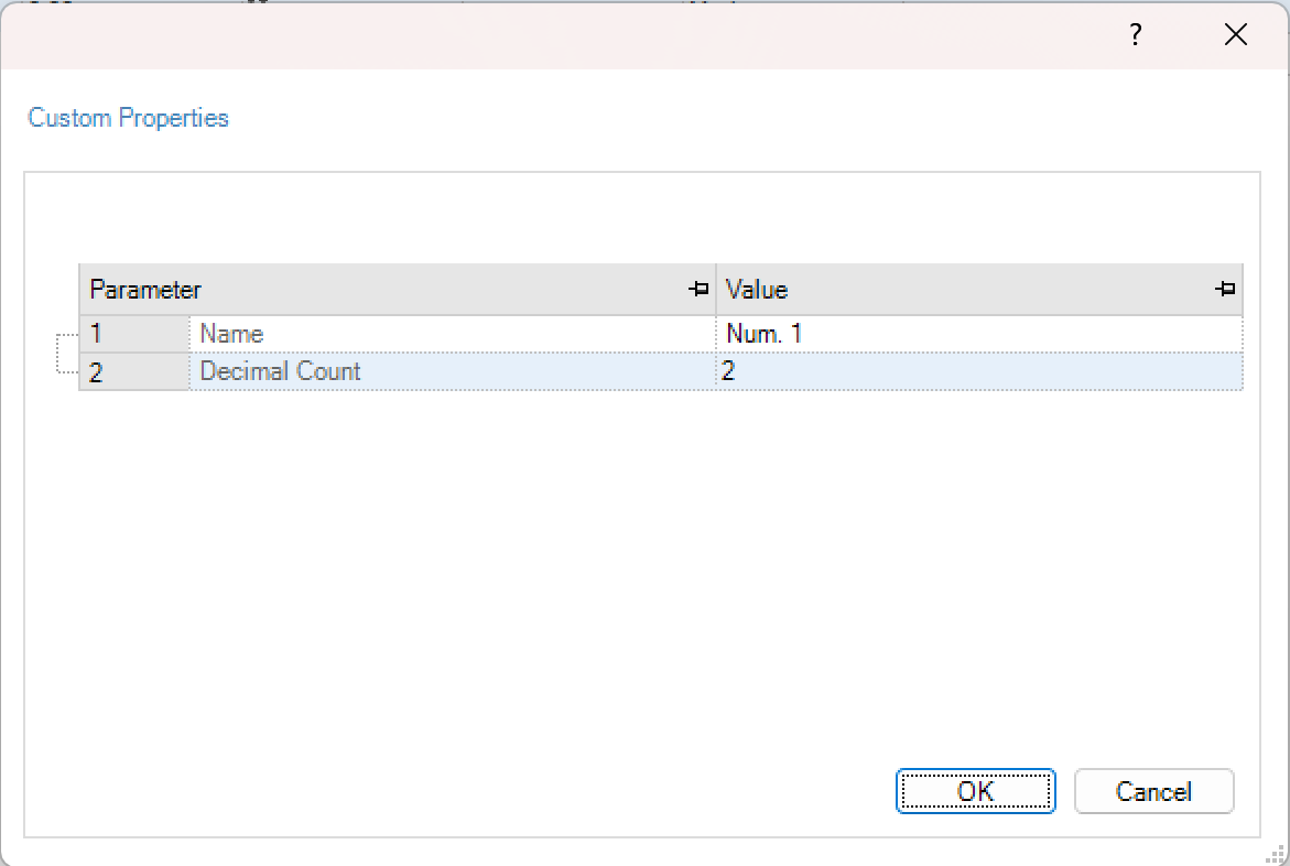
Edit tag properties: In addition to being used in picture elements such as normal process variables, the tag properties can be read and written using new drivers (DotNet) or using script commands.
Reading of tag properties
If a tag property is added to a variable, it can be read out in a control at runtime.To do this, after selecting the variable, the respective tag property that is to be displayed must be selected in the selection window (switch to the tab “properties”) at the top right. This is then displayed in conjunction with the name of the variable in the control.


Output in the runtime, is the value stored in tag property.
Export and import of process variables
In addition to editing the process variables in the designer, the user can also import and export variables into an Excel table. The exported file format is an XML file that can already be called from the Designer.
Important
If an XML file generated by the export is processed with Excel, it must be ensured that if I want to delete the value in a cell, it must be replaced with a “’”. Otherwise, the complete variable will be deleted.
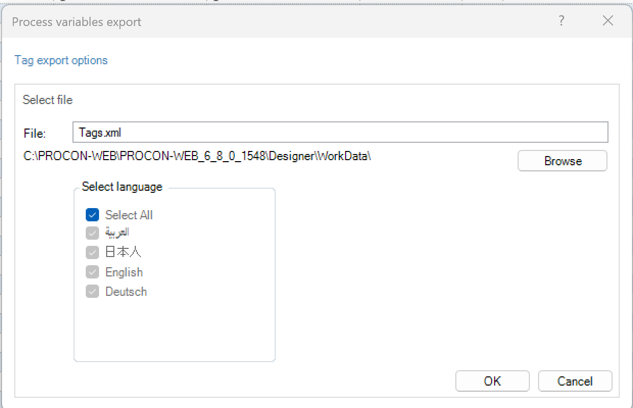
Within the dialogue of the import of process variables you can choose XML (PROCON-WIN 5.7 or PROCON-WEB 6) as well as CSV-files from older versions (only PROCON-WIN 3.10 / PROCON-WIN 4.10!).


Via “Browse” you can search for and select the file to be imported in the file directory.
It is possible to prefix the imported variables, for example to store the origin of these variables in the variable name. An incorrect entry in the “Prefix” field will cause the OK button to be deactivated and a message will appear indicating the incorrect entry.
If a CSV file is imported, it must be specified whether the variables to be imported are numeric, logical or strings. For each species, you have to import a separate CSV file here!The following information is not included in the CSV import:
Structure assignments
Permissions
PC-Name
VDMAXML_P
Unit
Important
There will be no units generated during the import. If a specific unit is not present within the project, no unit will be assigned. However, after importing there will be information about the variables, where importing the unit was not possible, including their names.”this is only possible with a structural level. New Structures with substructures are not created when importing variables and the variables also not imported. To do this, the structures in PROCON-WEB must be present
External coupling (driver)
Driver coupling (PLC)
To be able to configure or establish a coupling with a PLC, the corresponding driver must first be selected in the Designer. Several drivers are integrated in PROCON-WEB for coupling the most common systems.
The driver selection is called up in the process variable editor via the entry in the ribbon menu or via the driver column in the tag grid.

By selecting the driver with the checkbox, the driver can be used in the project after confirming with “OK”.
Important
Up to eight different drivers can be used in a project, depending on the license.
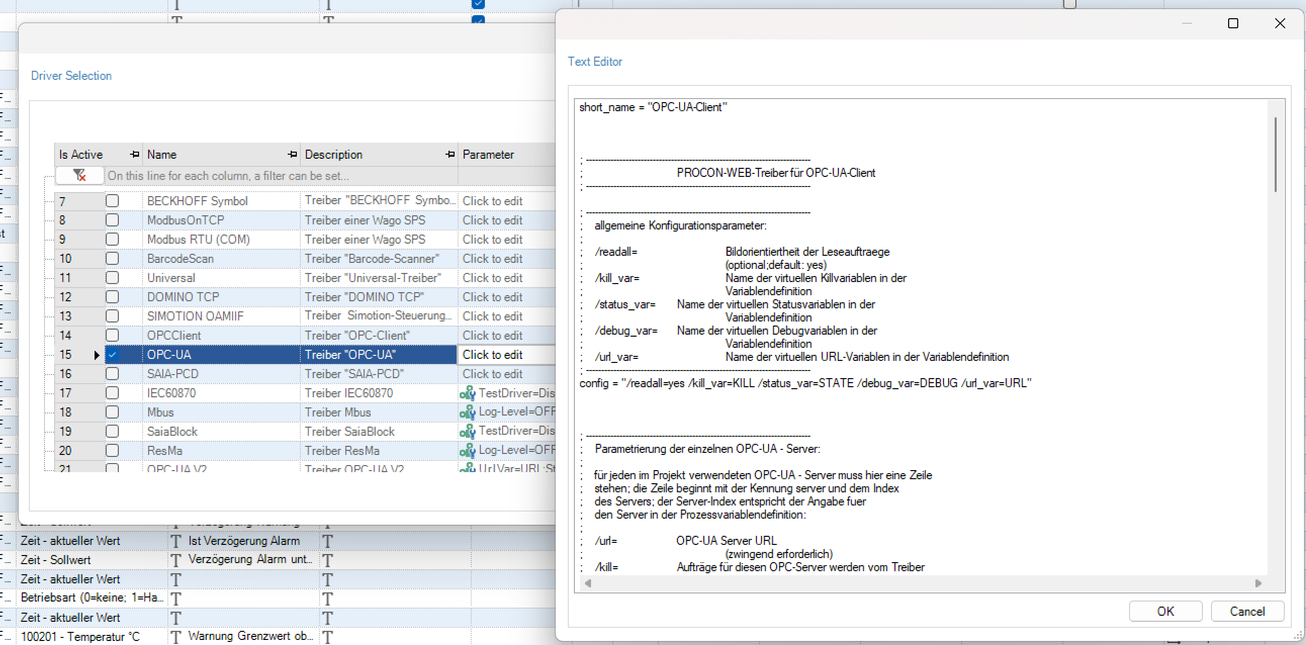
For the coupling to work, some of the drivers must be further configured.With older drivers, this is done using a driver’s own ini file. This ini file can also be edited using the driver selection dialog:
In the case of IP-based drivers, the address of the controller, for example, must be adapted if necessary. For more information, please refer to the manual for the corresponding driver.
With some drivers there is also the option of transferring the variable definitions used on the control directly into PROCON-WEB. For this see chapter process coupling.
With newer drivers, the configuration is better supported by a new driver interface. See the chapter on this process coupling – the new driver interface.
SPS-Import
The PLC import is used to transfer the variable definition used on the controller directly into PROCON-WEB. This can prevent any incorrect definitions or incorrect configurations of the variables. The PLC import is only available for the most frequently used drivers. The following table lists the meaning of the columns in the process variable editor.
The PLC import tab is opened via the PLC import ribbon tool in the tag tools.
Important
The driver-dependent variable import is only possible if the corresponding driver is activated in the driver selection.
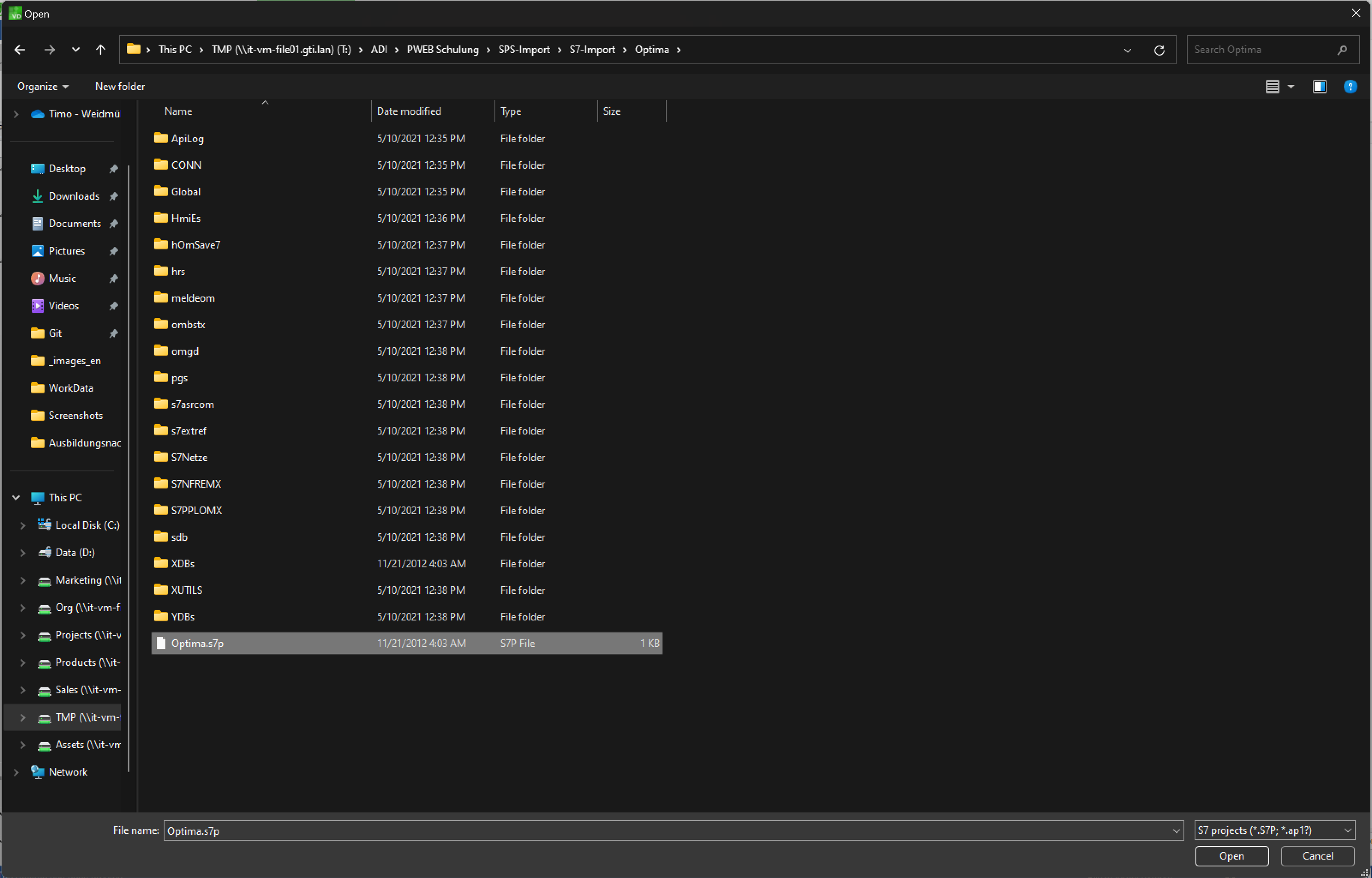
The procedure for driver-dependent variable import is described here as an example for S5 / S7-Combi RFC1006. Import of variables of other PLC types can be found in the corresponding driver manual.
The S7 project from which the tags are to be imported is selected in the “Import Settings” window using the “Add” button.

The corresponding S7 project is selected in the following dialog.
After opening the S7 project, the flags, inputs, outputs and DBs to be imported can be selected. The AG can already be predefined under the AG column. The selected variables from the project are read into PROCON-WEB via “Read symbols”.

In the right area or the import settings the existing connections to the PLC can be created, edited or deleted. Next to the sources are the structures of the imported values displayed, if there are any. Structures that are only in the PLC-project available are green highlighted, if they are in the SPS and project identically they are gray. Structures that are in both present but differently are without highlighting and black font colour.
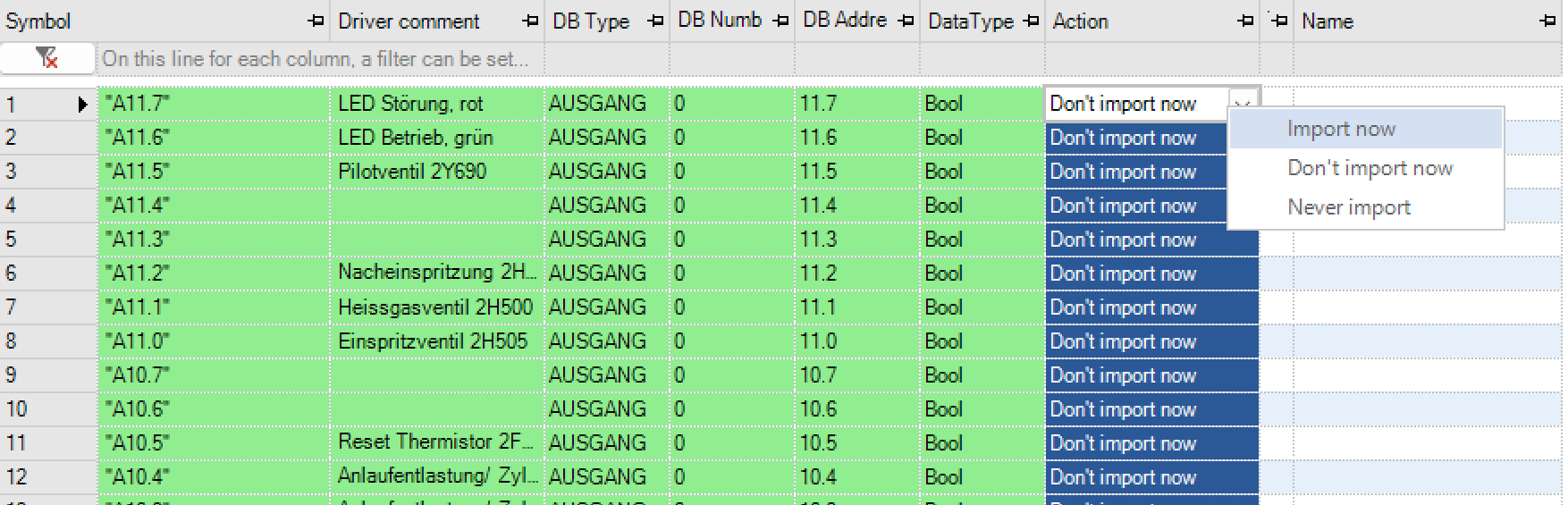
The variables read in are displayed in the work area. Via the “Action” column or the context menu of the right mouse button, you can select whether the variable should be imported.
Important
There will be no units generated during the import. If a specific unit is not present within the project, no unit will be assigned. However, after importing there will be information about the variables, where importing the unit was not possible, including their names.
The available import options are shown in the table below.
Option |
Meaning |
|---|---|
Num. Class, log. Class, text class |
Selection of the corresponding variable classes for import |
Manage classes |
Create and edit variable classes |
Adopt min / max from PLC |
Adopt the min / max values from PLC variables |
Accept decimal places from PLC |
Accept the decimal places from the PLC variables |
Accepts comment from the PLC |
Accepts the comments of the variables from the PLC |
Cut off block names |
With this option only the variable names are displayed in the DBs |
Show identical |
Shows the variables that are identical in the PLC and PROCON-WEB project |
Show not identical |
Shows the variables that are not identical in the PLC and PROCON-WEB project |
New ads |
Shows all new variables (not yet imported) |
Show deleted |
Shows all previously imported variables that were deleted in the PROCON-WEB project |
Automatically assign existing process variables to the PLC symbols |
If variables have already been configured that have an identical address to the PLC symbols, they are automatically assigned here |
PLC structure import: With drivers such as 3S Arti, 3S PLC-Handler or Beckhoff Symbol, it is possible to import structures that are defined in the control program and to assign them to the corresponding variables. To do this, the driver must first be selected in the driver selection
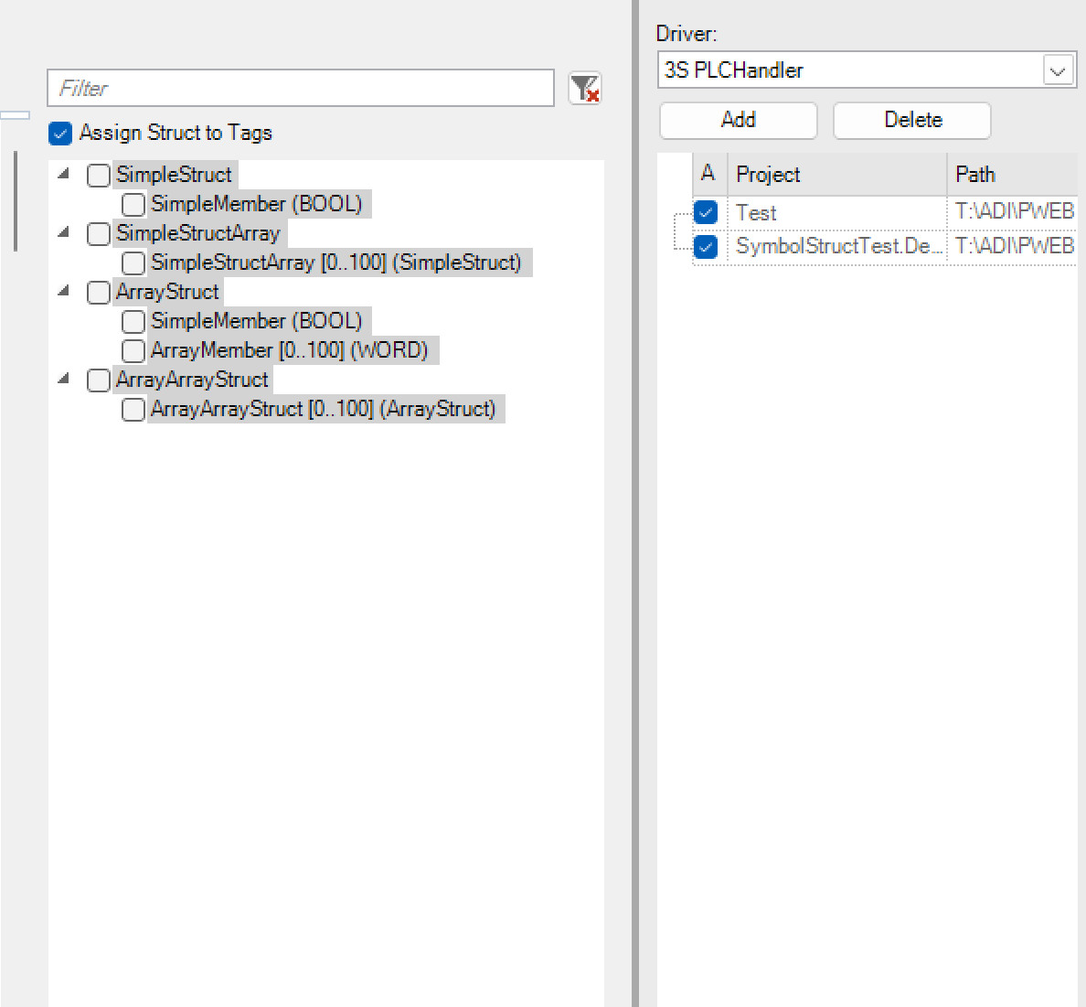
The structures in the PLC project are displayed in the main window of the PLC import after the symbols have been read in with the “Show structures” option. The required structures are selected using the checkboxes. If not all sub-elements are required, the structure can only be partially imported. After selecting the structural element, the structures can be imported with “Import structures”.
Important
The PLC structure import can take a few minutes depending on the nesting.
The different colours have the following meanings:
Green: Structures or their parameters weren´t yet imported into the project
Light gray: Structures or their parameters were already imported into the project
Dark gray: Structures or their parameters are already existing in the project, but with differences like number of elements or changes in the sub-structuresAfter importing the structures, the option “Assign structures to variables” is available. With this option, the system creates the corresponding instances of the structure during the tag import and assigns them to the tags.
Important
The variables can only be automatically assigned to the structures once the structures have been imported. If the variables are imported before the structures, the assignment must be made manually.
Update PLC import
If variables have already been imported or created in PROCON-WEB and the associated PLC program has been changed, the variables can be updated by another import.The import recognises whether the variables to be imported from the PLC program already exist or not.

Depending on whether the variable already exists or not, the import offers various options on how to deal with these variables.
This also makes it possible to make changes to variables that were made in the PLC program in PROCON-WEB, e.g., changes to addresses etc.
Driver interface
PROCON-WEB provides an interface for some newer drivers. This interface should enable a closer coupling between the designer and the driver as well as a departure from the “driver.ini”.Connections for the new drivers can be created and parameterised via the driver dialog.

Creation of connections
If the driver supports connections, the dialog for defining connections can be opened via the driver dialog or the tag grid.New connections are created either via the context menu or via the “New” button.

Driver-specific parameters
For the drivers based on the new driver interface, there may be driver-specific parameters that apply to all connections of the driver. These parameters are also edited via a dialog.

System variables
System variables in general
System variables were introduced with PROCON-WEB. These system variables allow access to system information that was previously either not received at all or was only received via scripts.
Some system variables are defined globally, i.e. they have the same value everywhere and in every client. Some system variables are locally valid, i.e. each client has its own variable management.
The list of system variables is constantly being updated and can therefore offer new options at any time. System variables are made available on a server-specific basis. The following lists only apply to the SCADA variant. Embedded targets support a different subset!
Local system variables
The following list gives a brief overview of local system variables
Name |
Display name |
Meaning |
|---|---|---|
__Alert_LastClientAText* |
$Alert.LastClientAText |
Last message text in the client language |
__Alert_LastClientIText* |
$Alert.LastClientIText |
Last info-text in the client language |
__Alert_LastClientLText* |
$Alert.LastClientLText |
Text last triggered type “Logging” in the client language |
__Alert_LastClientMText* |
$Alert.LastClientMText |
Last message text in the client language |
__Alert_LastClientSText* |
$Alert.LastClientSText |
Text last triggered Type “Status” in the client language |
__Alert_LastClientText* |
$Alert.LastClientText |
Last text of all pending alarms in the client language |
__Alert_LastClientTText* |
$Alert.LastClientTText |
Text last triggered Type “Times” in the client language |
__Alert_LastClientVText* |
$Alert.LastClientVText |
Text last triggered Type “Availability” in the client language |
__Alert_LastClientWText* |
$Alert.LastClientWText |
Last Alert Text in the client language |
__Alert_LastClientZText* |
$Alert.LastClientZText |
Text last triggered Type “Machine times” in the client language |
__Client_Name |
$Client.Name |
Display of the client name |
__CurrentLanguage* |
$CurrentLanguage |
Display of the currently set language |
__CurrentUser_FullName* |
$CurrentUser.FullName |
Full name of the current user |
__CurrentUser_InactiveSeconds |
$CurrentUser.InactiveSeconds |
Time in seconds since the last operator action of the currently logged on user |
__CurrentUser_IsOnline* |
$CurrentUser.IsOnline |
Indicates whether a user is online |
__CurrentUser_LastLogin* |
$CurrentUser.LastLogin |
Last login of the current user in seconds since 1/1/1970” |
__Navigation_CurrentView |
$Navigation.CurrentView |
Number of the currently displayed navigation view |
__Navigation_ElementActive |
$Navigation.ElementActive |
Indicates whether a navigation element is currently active (selected) |
__Navigation_ElementActivePost |
$Navigation.ElementActivePost |
Indicates whether a subsequent navigation element is currently active (selected) |
__Navigation_ElementActivePre |
$Navigation.ElementActivePre |
Indicates whether a previous navigation element is currently active (selected) |
__Navigation_ElementDisabled |
$Navigation.ElementDisabled |
Indicates whether a navigation element is currently locked |
__System_MessageBoxDisable |
$System.MessageBoxDisable |
Messagebox active or not |
__System_UTCProjectExportDate |
$System.UTCProjectExportDate |
The time when the project was exported as a timestamp in Milliseconds |
Globale Systemvariablen
The following list gives a brief overview of global system variables
Name |
Display name |
Meaning |
|---|---|---|
__Alert_Ack* |
$Alert.Ack |
Global acknowledgment variable 1 = most recent message, 2 = all messages |
__Alert_AckA* |
$Alert.AckA |
Global acknowledgment variable for all messages |
__Alert_AckL* |
$Alert.AckL |
Global acknowledgment variable for messages of the type “Logging” |
__Alert_AckM* |
$Alert.AckM |
Global acknowledgment variable for messages |
__Alert_AckI* |
$Alert.AckI |
Global acknowledgment variable for messages of the type “Info” |
__Alert_AckS* |
$Alert.AckS |
Global acknowledgment variable for messages of the type “State” |
__Alert_AckT* |
$Alert.AckT |
Global acknowledgment variable for messages of the type “Times” |
__Alert_AckV* |
$Alert.AckV |
Global acknowledgment variable for messages of the type “Availability” |
__Alert_AckW* |
$Alert.AckW |
Global acknowledgment variable for warnings |
__Alert_AckZ* |
$Alert.AckZ |
Global acknowledgment variable for messages of the type “machine types” |
__Alert_Count* |
$Alert.Count |
Number of all pending message types |
__Alert_CountA* |
$Alert.CountA |
Number of pending alarms |
__Alert_CountI* |
$Alert.CountI |
Number of pending messages of the type “Info” |
__Alert_CountL* |
$Alert.CountL |
Number of pending messages of the type “Logging” |
__Alert_CountM* |
$Alert.CountM |
Number of pending messages |
__Alert_CountS* |
$Alert.CountS |
Number of pending messages of the type “State” |
__Alert_CountT* |
$Alert.CountT |
Number of pending messages of the type “Times” |
__Alert_CountV* |
$Alert.CountV |
Number of pending messages of the type “Availability” |
__Alert_CountW* |
$Alert.CountW |
Number of pending messages |
__Alert_CountZ* |
$Alert.CountZ |
Number of pending messages of the type “Machine times” |
__Alert_Language |
$Alert.Language |
Language Specification for Global Message Types |
__Alert_LastANr* |
$Alert.LastANr |
Last message number |
__Alert_LastAText* |
$Alert.LastAText |
Last message text |
__Alert_LastATime* |
$Alert.LastATime |
Last alarm triggering time |
__Alert_LastINr* |
$Alert.LastINr |
Last Message Number of type “Info” |
__Alert_LastIText* |
$Alert.LastIText |
Last info-text |
__Alert_LastITime* |
$Alert.LastITime |
Trigger time last message of type “Info” |
__Alert_LastLNr* |
$Alert.LastLNr |
Number last triggered type “Logging” |
__Alert_LastLText* |
$Alert.LastLText |
Text last triggered type “Logging” |
__Alert_LastLTime* |
$Alert.LastLTime |
Time of the last triggered alarm of the type “Logging” |
__Alert_LastMNr* |
$Alert.LastMNr |
Last message number |
__Alert_LastMText* |
$Alert.LastMText |
Last message text |
__Alert_LastMTime* |
$Alert.LastMTime |
Last Notification Trigger Time |
__Alert_LastNr* |
$Alert.LastNr |
Last number of all pending alarms |
__Alert_LastSNr* |
$Alert.LastSNr |
Number last triggered Type “Status” |
__Alert_LastSText* |
$Alert.LastSText |
Text last triggered Type “Status” |
__Alert_LastSTime* |
$Alert.LastSTime |
Time last triggered message of the type “Status” |
__Alert_LastText* |
$Alert.LastText |
Last text of all pending alarms |
__Alert_LastTime* |
$Alert.LastTime |
Last alarm triggering time |
__Alert_LastTNr* |
$Alert.LastTNr |
Number last triggered Type “Times” |
__Alert_LastTText* |
$Alert.LastTText |
Text last triggered Type “Times” |
__Alert_LastTTime* |
$Alert.LastTTime |
Time last triggered message of the type “Times” |
__Alert_LastVNr* |
$Alert.LastVNr |
Number last triggered Type “Availability” |
__Alert_LastVText* |
$Alert.LastVText |
Text last triggered Type “Availability” |
__Alert_LastVTime* |
$Alert.LastVTime |
Time last triggered message of the type “Status” |
__Alert_LastWNr* |
$Alert.LastWNr |
Last Alert Number |
__Alert_LastWText* |
$Alert.LastWText |
Last Alert Text |
__Alert_LastWTime* |
$Alert.LastWTime |
Trigger time last warning |
__Alert_LastZNr* |
$Alert.LastZNr |
Number last triggered Type “Machine times” |
__Alert_LastZText* |
$Alert.LastZText |
Text last triggered Type “Machine times” |
__Alert_LastZTime* |
$Alert.LastZTime |
Time last triggered Type “Machine times” |
__Alert_LastExt1* |
$Alert.LastExt1 |
External Info 1 of the last triggered global type |
__Alert_LastAExt1* |
$Alert.LastAExt1 |
External Info 1 of the last triggered alarm |
__Alert_LastIExt1* |
$Alert.LastIExt1 |
External Info 1 of the last triggered type „Info“ |
__Alert_LastLExt1* |
$Alert.LastLExt1 |
External Info 1 of the last triggered type “Logging |
__Alert_LastMExt1* |
$Alert.LastMExt1 |
External Info 1 of the last triggered message |
__Alert_LastSExt1* |
$Alert.LastSExt1 |
External Info 1 of the last triggered state |
__Alert_LastTExt1* |
$Alert.LastTExt1 |
External Info 1 of the last triggered type “Times” |
__Alert_LastVExt1* |
$Alert.LastVExt1 |
External Info 1 of the last triggered type „Availability“ |
__Alert_LastWExt1* |
$Alert.LastWExt1 |
External Info 1 of the last triggered type “Warning” |
__Alert_LastZExt1* |
$Alert.LastZExt1 |
External Info 1 of the last triggered type “Machine times” |
__Alert_LastExt2* |
$Alert.LastExt2 |
External Info 2 of the last triggered global type |
__Alert_LastAExt2* |
$Alert.LastAExt2 |
External Info 2 of the last triggered alarm |
__Alert_LastIExt2* |
$Alert.LastIExt2 |
External Info 2 of the last triggered type “Info” |
__Alert_LastLExt2* |
$Alert.LastLExt2 |
External Info 2 of the last triggered type “Logging” |
__Alert_LastMExt2* |
$Alert.LastMExt2 |
External Info 2 of the last triggered message |
__Alert_LastSExt2* |
$Alert.LastSExt2 |
External Info 2 of the last triggered state |
__Alert_LastTExt2* |
$Alert.LastTExt2 |
External Info 2 of the last triggered type “Times” |
__Alert_LastVExt2* |
$Alert.LastVExt2 |
External Info 2 of the last triggered type “Availability” |
__Alert_LastWExt2* |
$Alert.LastWExt2 |
External Info 2 of the last triggered type “Warning” |
__Alert_LastZExt2* |
$Alert.LastZExt2 |
External Info 2 of the last triggered type “machine times” |
__Alert_LastExt3* |
$Alert.LastExt3 |
External Info 3 of the last triggered global type |
__Alert_LastAExt3* |
$Alert.LastAExt3 |
External Info 3 of the last triggered alarm |
__Alert_LastIExt3* |
$Alert.LastIExt3 |
External Info 3 of the last triggered type “Info” |
__Alert_LastLExt3* |
$Alert.LastLExt3 |
External Info 3 of the last triggered type “Logging” |
__Alert_LastMExt3* |
$Alert.LastMExt3 |
External Info 3 of the last triggered message |
__Alert_LastSExt3* |
$Alert.LastSExt3 |
External Info 3 of the last triggered state |
__Alert_LastTExt3* |
$Alert.LastTExt3 |
External Info 3 of the last triggered type “Times” |
__Alert_LastVExt3* |
$Alert.LastVExt3 |
External Info 3 of the last triggered type “Availability” |
__Alert_LastWExt3* |
$Alert.LastWExt3 |
External Info 3 of the last triggered type “Warning” |
__Alert_LastZExt3* |
$Alert.LastZExt3 |
External Info 3 of the last triggered type “Machine times” |
__Alert_LastExt4* |
$Alert.LastExt4 |
External Info 4 of the last triggered global type |
__Alert_LastAExt4* |
$Alert.LastAExt4 |
External Info 4 of the last triggered alarm |
__Alert_LastIExt4* |
$Alert.LastIExt4 |
External Info 4 of the last triggered type “Info” |
__Alert_LastLExt4* |
$Alert.LastLExt4 |
External Info 4 of the last triggered type “Logging” |
__Alert_LastMExt4* |
$Alert.LastMExt4 |
External Info 4 of the last triggered message |
__Alert_LastSExt4* |
$Alert.LastSExt4 |
External Info 4 of the last triggered state |
__Alert_LastTExt4* |
$Alert.LastTExt4 |
External Info 4 of the last triggered type “Times” |
__Alert_LastVExt4* |
$Alert.LastVExt4 |
External Info 4 of the last triggered type “Availability” |
__Alert_LastWExt4* |
$Alert.LastWExt4 |
External Info 4 of the last triggered type “Warning” |
__Alert_LastZExt4* |
$Alert.LastZExt4 |
External Info 4 of the last triggered type “Machine times” |
__Alert_LastExt5* |
$Alert.LastExt5 |
External Info 5 of the last triggered global type |
__Alert_LastAExt5* |
$Alert.LastAExt5 |
External Info 5 of the last triggered alarm |
__Alert_LastIExt5* |
$Alert.LastIExt5 |
External Info 5 of the last triggered type “Info” |
__Alert_LastLExt5* |
$Alert.LastLExt5 |
External Info 5 of the last triggered type “Logging” |
__Alert_LastMExt5* |
$Alert.LastMExt5 |
External Info 5 of the last triggered type “Message” |
__Alert_LastSExt5* |
$Alert.LastSExt5 |
External Info 5 of the last triggered state |
__Alert_LastTExt5* |
$Alert.LastTExt5 |
External Info 5 of the last triggered type “Times” |
__Alert_LastVExt5* |
$Alert.LastVExt5 |
External Info 5 of the last triggered type “Availability” |
__Alert_LastWExt5* |
$Alert.LastWExt5 |
External Info 5 of the last triggered type “Warning” |
__Alert_LastZExt5* |
$Alert.LastZExt5 |
External Info 5 of the last triggered type “Machine times” |
__Current_UTCTime* |
$Current.UTCTime |
Current UTC-Tim in milliseconds since 1/1/1970” |
__TagServer_DriverCount* |
$TagServer.DriverCount |
Number of active drivers in the TagServer |
__TagServer_DriverXXXX_Name |
$TagServer.DriverXXXX_Name |
Name of the driver |
__TagServer_DriverXXXX_Number |
$TagServer.DriverXXXX_Number |
Number of the driver |
__TagServer_DriverXXXX_CycleTime |
$TagServer.DriverXXXX_CycleTime |
Cycle time of the driver |
__TagServer_DriverXXXX_IsDemo |
$TagServer.DriverXXXX_IsDemo |
Specifies whether the driver is running as a demo driver |
__TagServer_DriverXXXX_IsNew |
$TagServer.DriverXXXX_IsNew |
Indicates whether it is a new .NET driver |
__TagServer_DriverXXXX_IsUsed |
$TagServer.DriverXXXX_IsUsed |
Indicates whether it is currently in use (there are variables that correspond to the drivers are assigned) |
__System_UTCStartTime* |
$System.UTCStartTime |
Shows the start time of the runtime (the TagServer is decisive) as UTC Time in milliseconds since 1.01.1970 on |
__System_ProjectName* |
$System.ProjectName |
Contain the name of the project |
__System_ProjectPath* |
$System.ProjectPath |
Contain the project path of the server |
__System_ProjectVersion* |
$System.ProjectVersion |
Contains the version of the project as string. |
__System_RuntimeVersion* |
$System.RuntimeVersion |
Contains the version number of the runtime (the TagServer version number) |
__Alert_TypeChar* |
$Alert.LastTypeChar |
The letter of the last message type. Value range: A,V,I,L,Z,M,S,T,W (text) |
Structures
Concept
In the structure editor, data structures composed of numerical, logical and text variables can be created. Any number of instances can be created from these structures. These instances can be assigned to so-called automation objects in the image montage. An automation object consists of a group of dynamization elements that are assigned to structural elements. The shown structure-class can not be edited.
Note
Data structures in PROCON-WEB primarily serve to reduce the project planning effort.
Information of the same type, such as actual values and setpoint values of a mixer, can be defined in structures. From this structure, the system can generate the corresponding number of instances and the corresponding process variables. The automation object of a mixer is created in the picture assembly. For this purpose, the elements of the mixer such as mixer symbol, actual value displays, setpoint inputs are combined into a group and assigned to a structure.The structural elements are assigned to the dynamic group elements, such as a setpoint. In the last step, an instance is assigned to the mixer automation object. Duplicates of the mixer can be created by copying the automation object and assigning the corresponding instance.
Important
Structure and instance information should preferably be generated via the tag import. The previously partially used functions for mapping variables to control addresses (e.g. in the case of Simatic S5 in DBs) are still available but not recommended and costly!
Processing of structures

To be able to create structures, the option “Create structure” is selected in the structure editor via the context menu and a name is given for the structure. Logical, numerical and text variable classes can be assigned to each structure. Furthermore, already existing structures for cascading can be inserted as a substructure, see chapter process coupling.

If no instance of a structure has been created, the order of the structure elements can be changed, or structure elements deleted.
**Meaning of the columns of a structure element:**The structure elements that can be created here are also process variable classes and serve as a template for the variables assigned to the instance
Column name |
Meaning |
|||||
|---|---|---|---|---|---|---|
Type |
Type |
des |
Structure elements |
(Numeric) |
Logisch, |
Text) |
Name |
Festlegen |
des |
Structure names |
und |
der |
Elements |
The structure name and the structure element name must be specified in the “Name” column. The “Type” column indicates the type of the structural element (logical, numerical, text)The contents of all other columns serve as a template for the instances and their process variables that will be created later via the system.
Column name |
Meaning |
|---|---|
Field size |
The field size indicates how many field elements XE “Field elements” with the same definition after this structural element. With a field size of 10, for example, 10 individual elements are obtained, but they all have the same minimum, maximum, default values, etc. |
Authorisation |
The value for the user authorisation can be between 0 and 255 |
Decimal places |
The number of desired decimal places must be specified here |
Min PLC |
Smallest possible value of the variable on the PLC |
Max PLC |
Laragest possible value of the variable on the PLC |
Min-PC |
The value to be displayed that is displayed in the runtime system when the minimum value is present |
Max-PC |
The value to be displayed that is displayed in the runtime system when the maximum value is present |
Default |
Standard value of the structure element |
Driver |
Communication driver |
E/A |
Structure element can be input, output or flag |
Field 0 |
driver-specific information |
Field 1 |
driver-specific information |
Field 2 |
driver-specific information |
Field 3 |
driver-specific information |
Markers (A to E) can be used in the driver-specific columns “Field 0” to “Field 3”. These marks are used to later calculate the resulting process variable addresses of the instances. In the marks “A” to “E”, the corresponding address index is mapped via the start address and the structure length. A value can be added to them within a structure element (e.g. A + 1, or A + 10). This value is used to define the start addresses of the process variables within an instance
If you are now working with labels and the process variables of the first instance are created by the system, then the variables are started to be generated with the specified start address of this label. In the process variables of the second instance, the label is replaced with the address = start address + structure length. All other instances are generated in the same way.
The start address and the structure length can be edited by selecting the structure with the right mouse button.The specified start address, and the structure length are shown in the top structure line in the corresponding columns field 1 to field 4 (e.g., A = 0; A: +10)
In the following dialog, as an example, the start address of the first instance is specified using the label “A” and the structure length for calculating the next instance

Important
Tags should not be used in columns with symbolic addressing.
Structure in structure
In PROCON-WEB, the user has the option of using existing structures as structural elements. The maximum nesting depth is up to nine substructures.
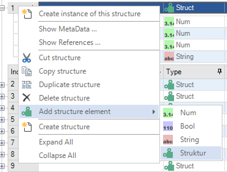
To insert a sub-structure, the option “Structure” is selected via the context menu under the entry “Insert structure element”. The structure selection dialog opens, in which all structures available in the project are listed. When a structure is selected, a clone of this structure is created internally. If changes are made to the sub-structure, the structure on which the sub-structure is based remains in its original state.
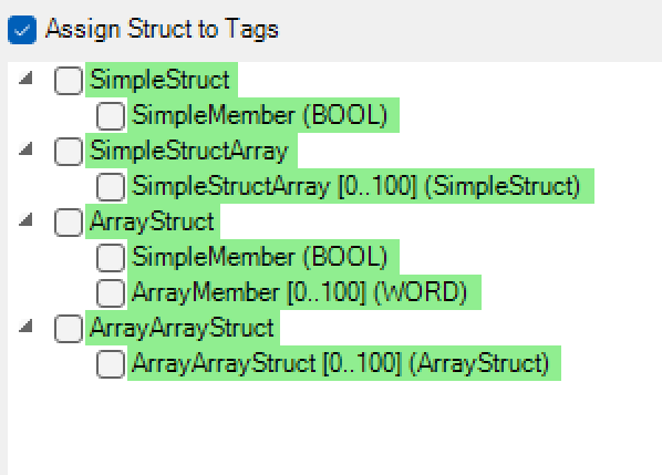
Array of Struct
In PROCON-WEB the user has the option of creating arrays of structures. This is done in the same way using the field size, for example with the variables.

In the assignment of the structure instance elements in the process variable editor, the arrays are marked accordingly with square brackets.

When assigning structure and instance, for example in the automation object, the arrays are also marked accordingly.

Deletion of structures
Structures can be deleted via the context menu of the right mouse button “Delete structure”. Please note that only unreferenced structures can be deleted. If there are instances of a structure, all instances of the structure must first be deleted.
Instances
To create instances of a structure, the relevant structure is selected and the option “Create instance of this structure” selected in the context menu. The “Add instance” dialog then opens.
The instance name and the number of instances to be created are specified in this dialog. If there are several instances, the system assigns a numbering after the instance name for each additional instance. The process variables for the new instance can also be created. The system assigns the name of the structure and the structure element as the variable name. The assignment to the corresponding instance is implemented in the “Structure instance element” column in the process variable list.
With “Use saved start address and structure length”, the start address, and structure length specified in the structure are used to calculate the process variable addressing of the instances. If this option is deselected, the start address is requested again for each instance. This makes it possible to create instances with process variables that are not stored one after the other in the control program within the structure length.
Deleting instances: To delete instances of structures, the corresponding instance is selected and selected using the “Delete instance” option.If variables are already referenced to the instance, the following dialog appears.
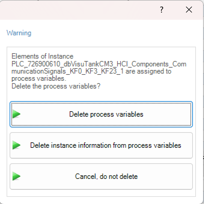
With this dialog the user can choose whether the referenced variables should be deleted or just the instance information should be removed. After selecting the respective option, the instance is deleted.
Important
You can only delete instances that are not assigned to an automation object!
Assignment of instances in the process variable editor In the process variable editor, process variables can be assigned to the corresponding structure instance via the “Structure instance element” column
